Buying another power supply for Pi-Top4

Im on vacation and just grabbed my PiTop and a generic USBC cord and power block when packing. I quicklly figured out it wasnt gonna work as my battery ran down on the Pi-Top that it requires some specific power. I found this on the Pi-Top web page:

“Your pi-top [4] will NOT work with most USB-C power supplies you might already own. You must use a power supply with USB-C Power Delivery specification at 15V, with minimum 30W for maximum accessory compatibility.”

I have a Best Buy around the corner but not sure WHICH one of the units available to Best Buy (see what I did there?) to buy…Here are the units Im choosing from at Best Buy:

https://www.bestbuy.com/site/searchpage.jsp?st=power+usbc+15v&_dyncharset=UTF-8&_dynSessConf=&id=pcat17071&type=page&sc=Global&cp=1&nrp=&sp=&qp=&list=n&af=true&iht=y&usc=All+Categories&ks=960&keys=keys

Can anyone give me quick guidance on which one to buy that will power my Pi-Top4 for my vacation without buying the wrong one?

Does it have to be EXACTLY 15V or at LEAST 15v or some variation?

Can someone point me in the right direction here? Please and thank you!

Fred

SOLVED:

For those of you that run into the same problem I took an educated guess at Best Buy and bought the:

“Insignia USB-C Wall Charger 45 Watt USB-C Charging with 3.0 Power Delivery [8ft]” and it works!

Good luck!

2 Likes

This one at Amazon works great. $20.00. Charges the pi-top slightly faster than the original. Meets all the specs and proper voltage output voltages.https://smile.amazon.com/gp/product/B07D64QLQ1/ref=ppx_yo_dt_b_asin_title_o01_s00?ie=UTF8&psc=1

@oviking99 what’s the charge time difference? I’d be surprised if there was any difference, the charge current is fixed internally and both chargers are more than capable of delivering the required power

I did not “test”. Agreed, the charge should be the same as you stated. Using the original charger it “seemed” to sit at 99% longer than the Amazon.

The Power Delivery specification requires communication between the device and the charger. The charger needs to know what voltage the device is asking for and the device needs to know what it can safely draw from the charger.

Because of lithium battery chemistry, I imagine that the pi-top prevents charging any faster than the “1 hr and 30 min” maximum. Although, if the charger cant deliver enough current, I suppose it might just take longer. But I havent tried to find out.

I did check yesterday to see what the actually charge voltage is and found it is 12v. IIRC, the website said we needed a PD charger that could supply 15v at nearly 40 watts, but 12v seems sufficient. I have a charger that will do 65 watts and up to 20.3v so I could power other things as well.

@Supernovali yes, that’s exactly right - charge current is limited but if the PSU can only supply a lower amount of current it will just take longer to charge. Powering the system (pi + accessories) will always take priority so what’s left over from that can be used to charge the battery.

We recommend 15 V because the USB-C spec states that 5V, 9V, 15V and 20V should be officially supported - the pi-top [4] can use either 12 V or 15 V, which is useful as some USB-C PD battery banks can only output 12 V (usually the ones only rated for 18 watts)

@duwudi Fascinating… does the charger handshake chip know it can change to the 15v spec? Or does it default to the 12v spec as long as it can reach 36 watts at 12v?

@Supernovali Yeah it’s configured to accept 12 or 15V - the standard maximum current of USB-C is 3A so if the charger is rated to 36 watt or less the 12V will always be able to deliver the same power as the 15V (only in the case of 45 watt would it make a difference).

Slight diversion of discussion if you’re interested :wink: :

If 12V is available we’ll use that because it’s more power-efficient to do so - this might seem counterintuitive since the higher voltage will need lower current and therefore they’ll be less ohmic heating. However, if we look at the various losses in a power converter, some are due to MOSFET conduction losses which are proportional to:

  • I_out^2 (always the same regardless of input voltage)
  • V_out/V_in for high-side MOSFET (meaning higher input voltage better)
  • (1 - V_out/V_in) for low-side MOSFET (meaning lower input voltage better)

and then there are switching losses which are proportional to V_in and I_out (or in the case of the low-side MOSFET no dependency on voltages at all). There is then a tonne of other smaller losses where V_in proportionality seems to dominate.

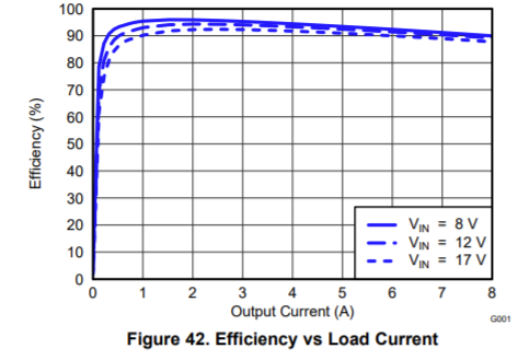
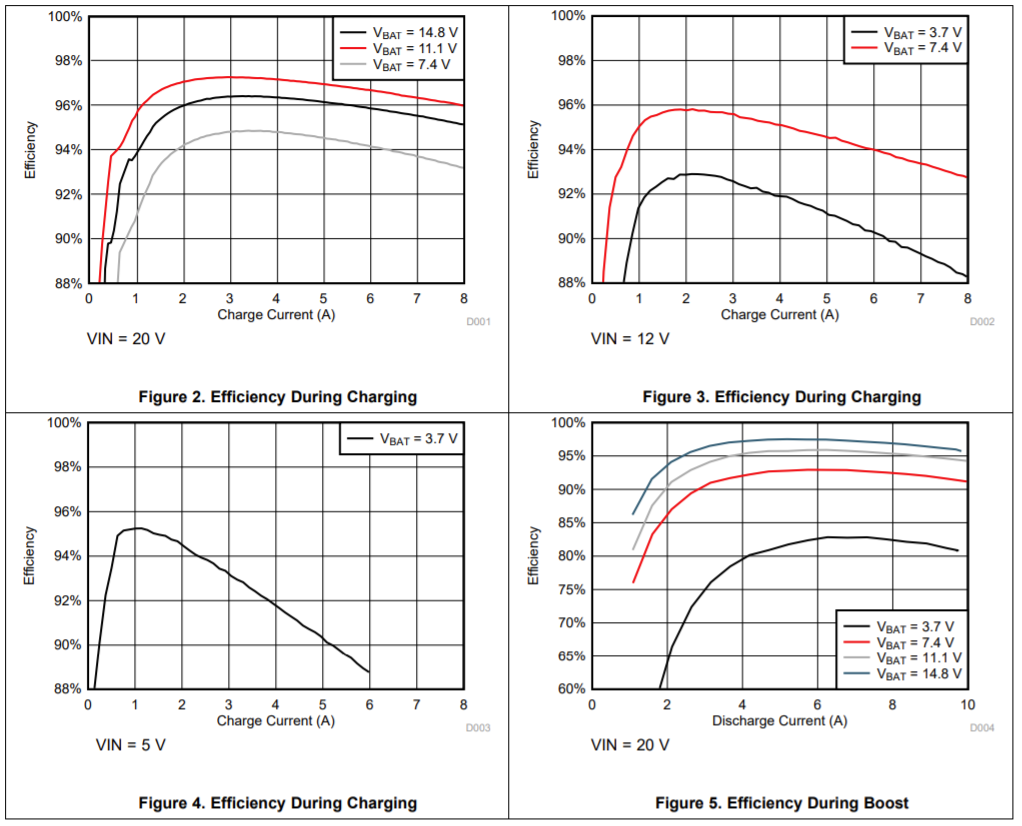
If we then look at some graphs from the IC datasheets this intuition seems to be verified by testing too.

This is for the 5V buck converter:

5%20V%20to%2017%20V%20Input%2C%208%20A%20Synchronous%20Step%20Down%20Converter%20With%20Hiccup%20da

This is the battery charger IC (ours is a 2S1P pack so V_BAT = 7.4V)

2021-02-07%2014_37_47-bq24780S%201-%20to%204-Cell%20Hybrid%20Power%20Boost%20Mode%20Battery%20Charge%20Controller%20With%20Pow

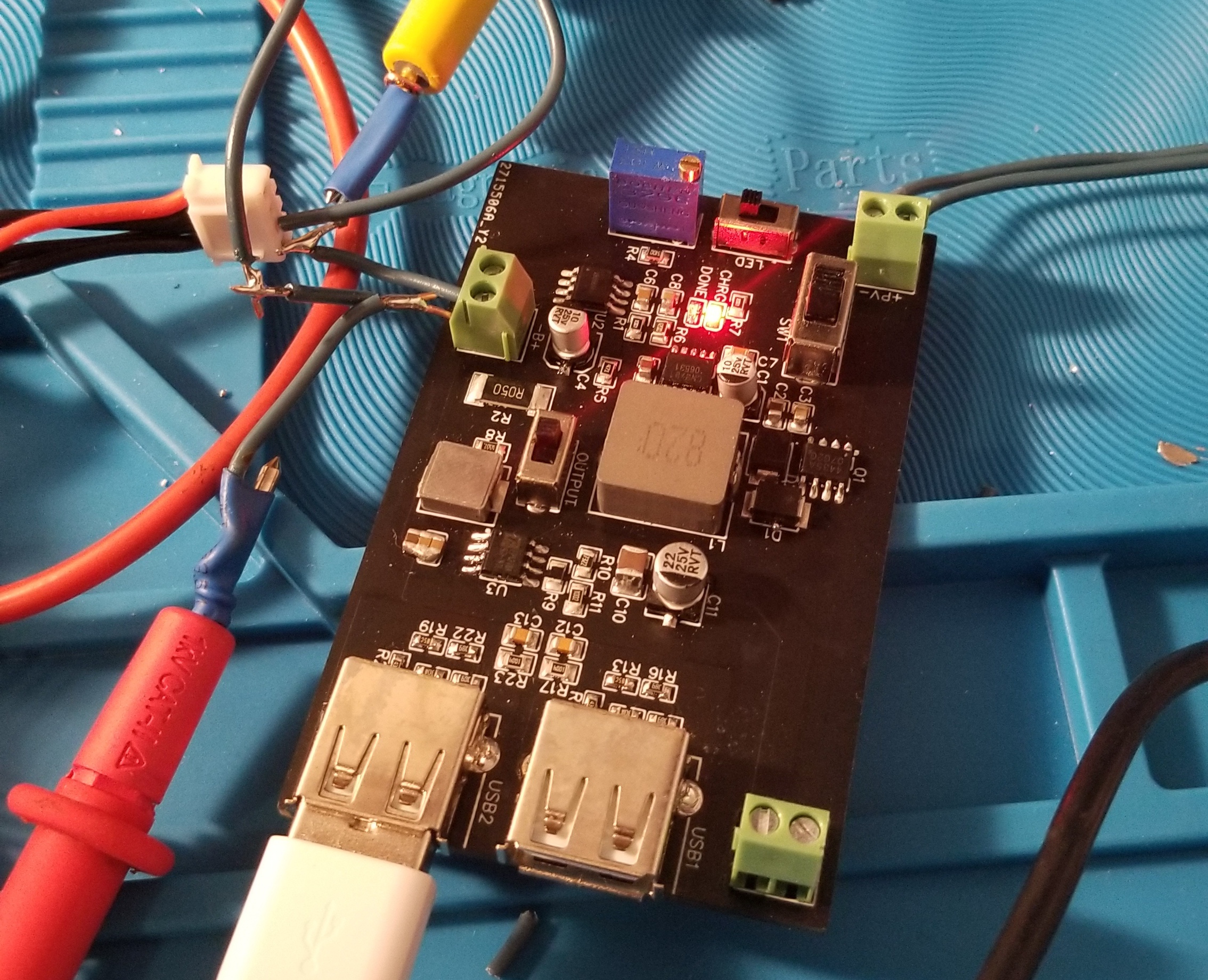
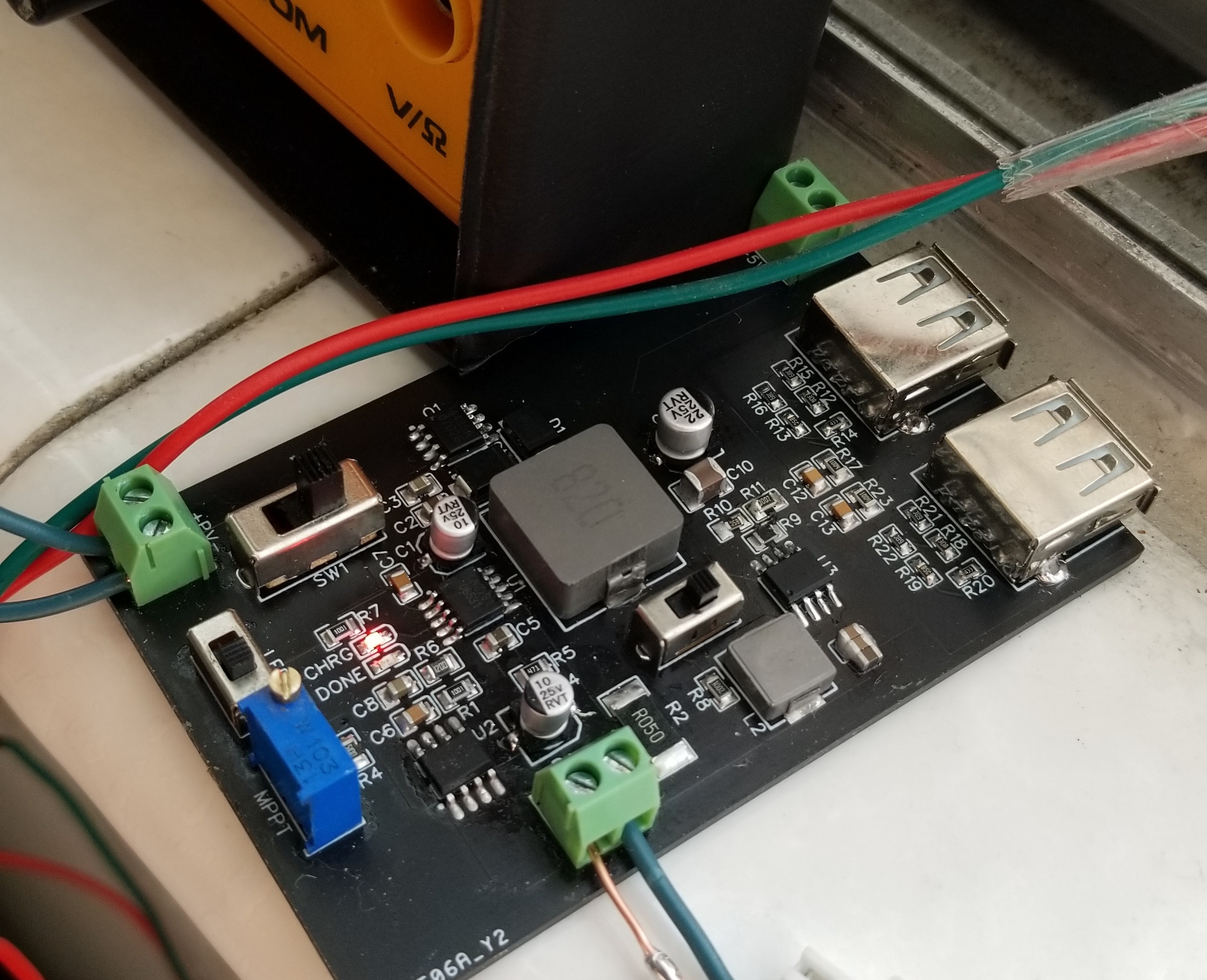
Yes indeed. Actually, I’ve also been working on a solar charge controller for somewhat higher powered microcontroller projects. I am using a buck converter for charging like you use for the pi-top but I am only using a single cell lipo for storage…

I am thinking of moving over to 2s as well since another buck converter would be more efficient than a boost converter. But it also increases complexity and cost as well, when a 10k mah single cell battery can be had for 10$.

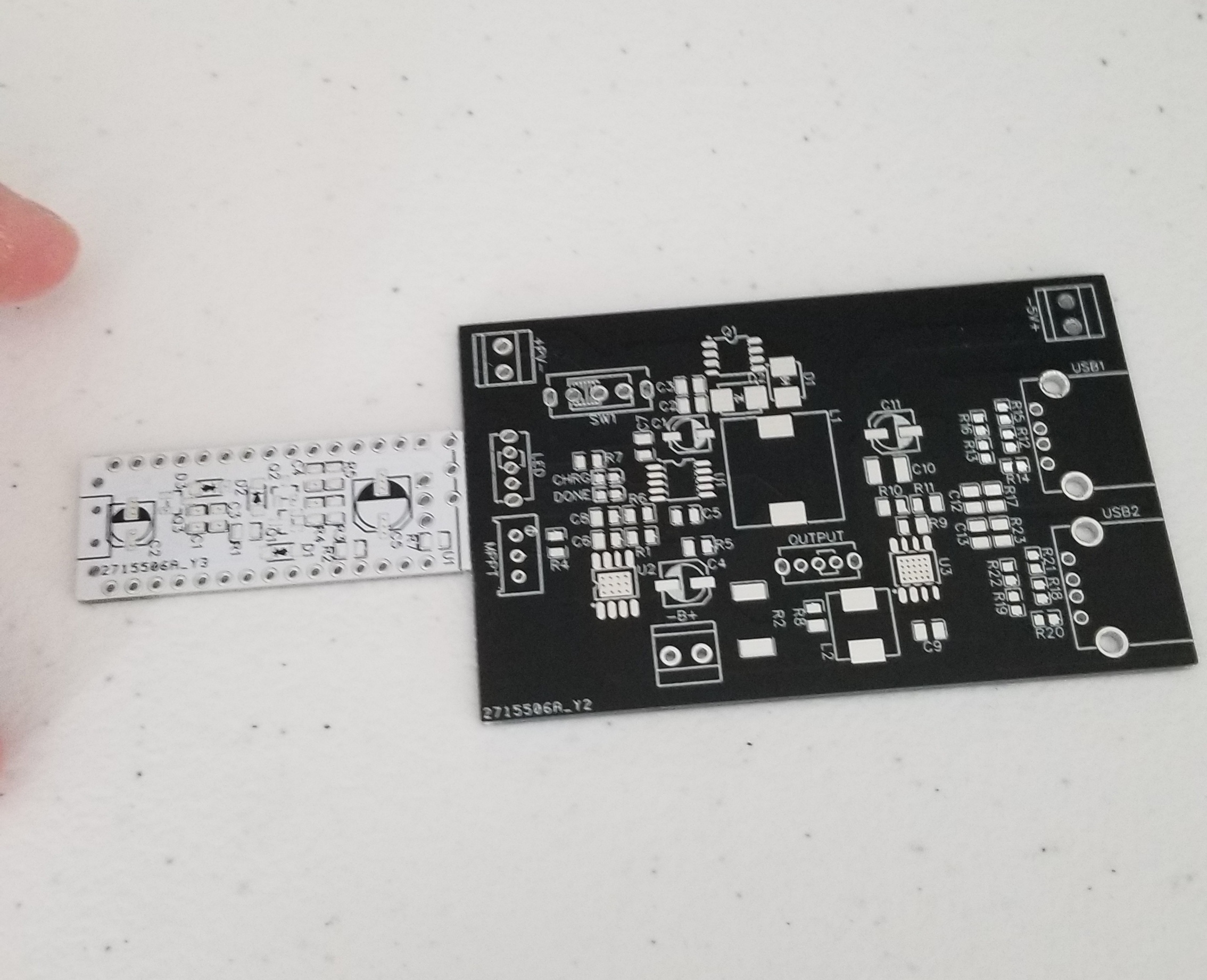
Still only a prototype. I have another project I’m also working on but I included it’s board for size comparison. This will probably get about 50% smaller when I’m done.
:slight_smile:
20210116_231105 20210118_122656 20210118_122700 20210118_122714

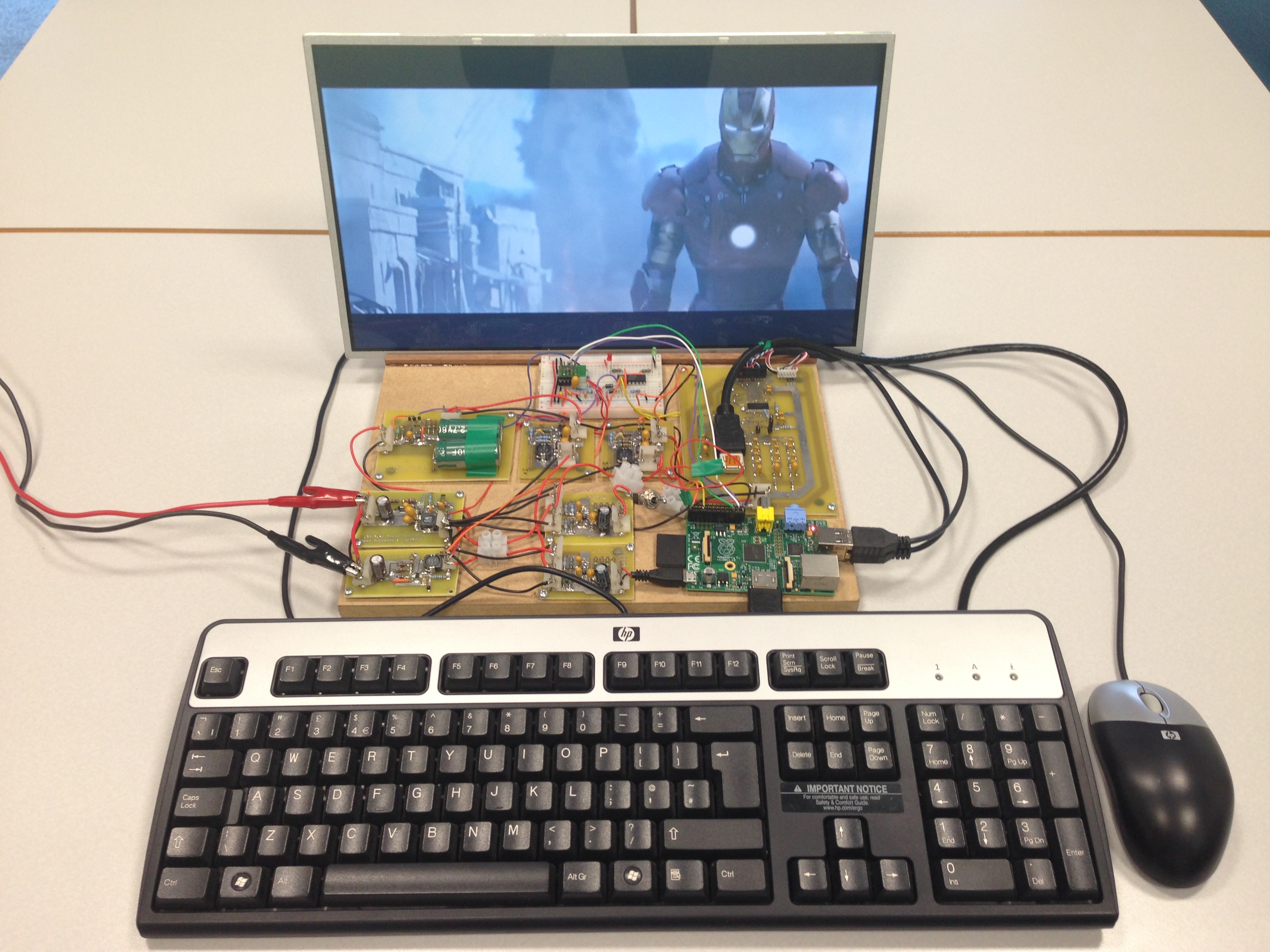
@Supernovali cool! It’s funny you mention solar charging, solar power was actually the genesis of the original pi-top concept - my 4th year engineering project at university was a solar-powered laptop based on the Raspberry Pi :grin:

Here it is nailed onto a piece of wood for the true “breadboard” look:

IMG_3465%20(1)

I actually used supercapacitors for energy storage, so I had a whopping 2 minutes of runtime if a cloud came overhead :laughing:

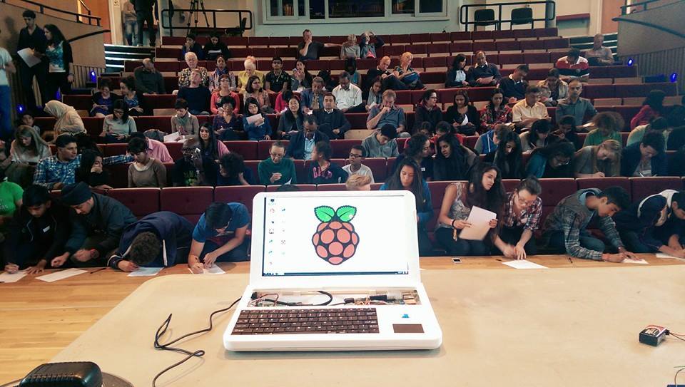
This then turned into a 3D printed laptop we used to teach with:

10552612_807361535953603_6232048309853121004_n%20(1)

which eventually changed colour to green (there is a funny story there too!):

20141007084825-pi-top-green-top

We launched this one on Indiegogo and it eventually became the Guinness world record for the worlds first 3D printed laptop! And of course, this then led to the original pi-top DIY laptop:

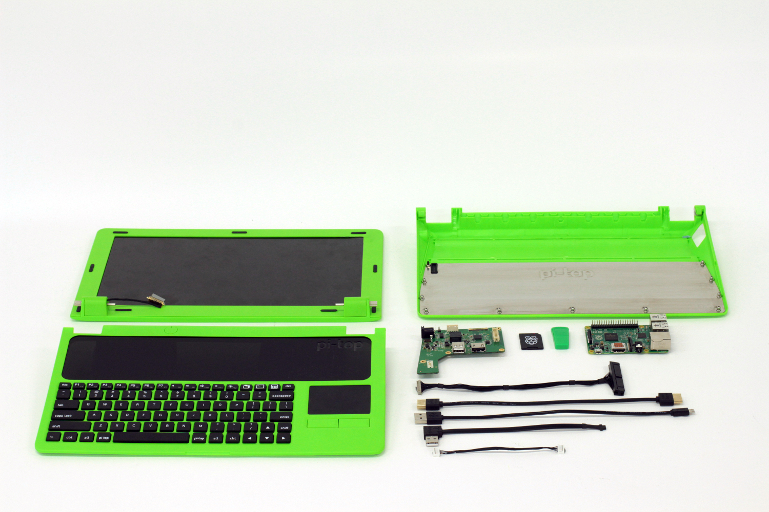
Pi-Top_Kit_Contents

AC_SL1500

Let me know if you want to discuss engineering architecture for any of your projects, would be happy to help!

2 Likes

I love it! I’ve seen the video’s for that model of pi-top. And I love it! And hey, on a mostly sunny day, 2 minutes should be adaquate :laughing:

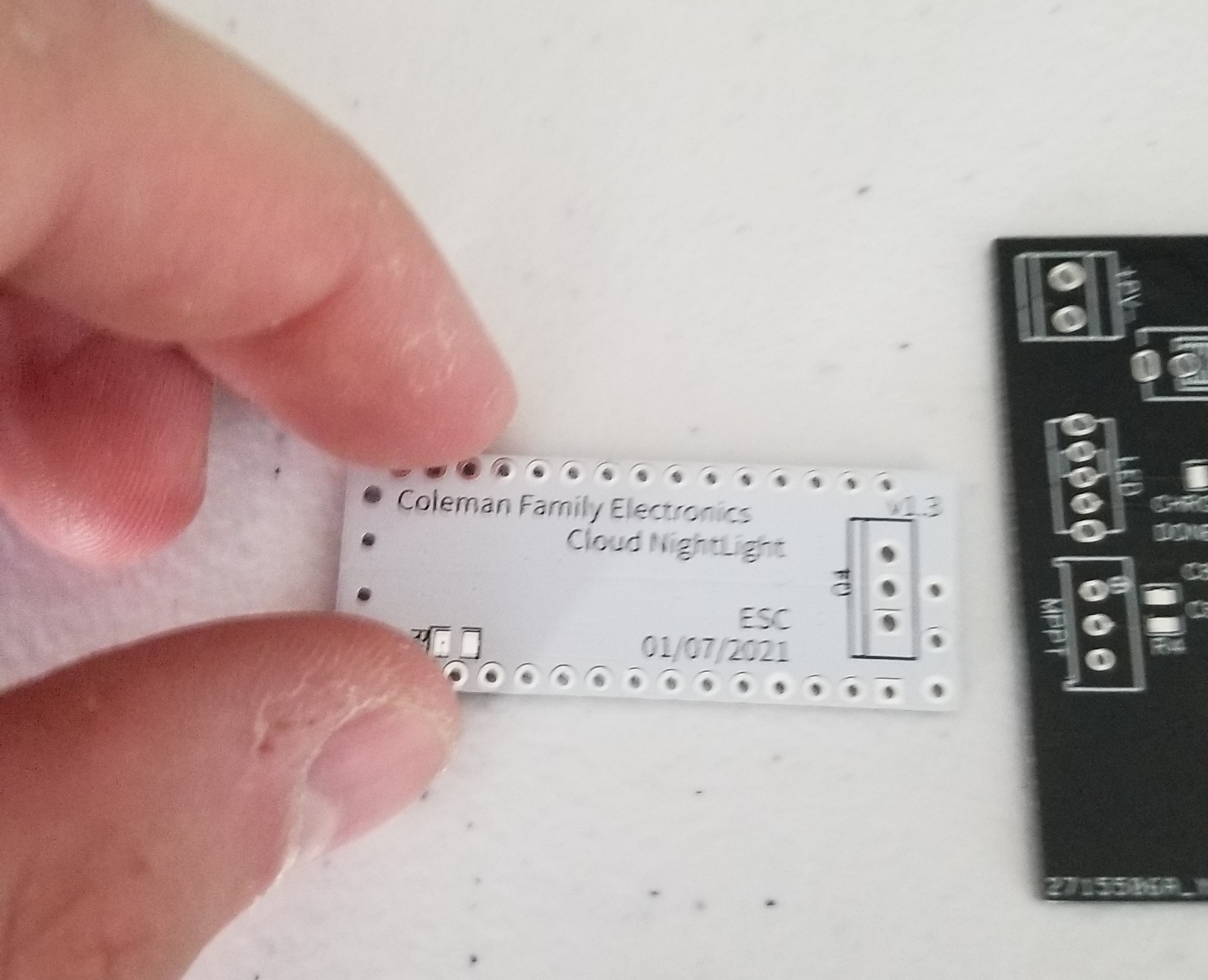
One of my bigger projects right now is a nightlight for my kiddo that is solar powered. I have it interfacing with google home, using FreeRTOS to run the setup. It’s using the WS2812B LED’s and needs a driver board to get the LED’s to stop drawing 1mA per led in the strip (with 150mA/150 LED’s. That small white board I was holding uses a logic level mosfet to achieve that. And the board acts as a shield for an arduino nano style board… at least for now. My plan is to make it a 1 board solution to reduce cost and eventually turn it into a sellable product. But that’s probably about 6 months out right now.

Sorry. I took this topic way off subject haha. We should start a new sub topic about projects people are currently working on for pointers and stuff haha

Hey all! it was great talking with you today @duwudi @Supernovali! I saw this power supply mentioned the other day and thought it might be relevant to the power supplies that were discussed today: https://twitter.com/Burgduino/status/1374120517091930113

1 Like

That power supply looks great for a raspberry pi! Unfortunately, it only supplies 5v, and the pi-top runs from a 2cell lipo. The charging circuit I’m working on can supply the energy needed for the pi-top :wink:

Although, it is using the ATTiny, which is being used for the USB power delivery that I plan on using, just not quite the same processor. I guess great minds think alike hehe

1 Like