Connecting New Motors and IMU

Hello Everyone,

I am writing this with regards to issues we are having with the Pi-Top4. We connected an MPU6050 to your GPIO pin slot but as a result, it burnt our sensor at 5V. We used this sensor on an Arduino beforehand and worked normally at 5V. Is it possible to connect an IMU to the GPIO slot and can you please if possible send a sample code for it? We do know there is an IMU in the expansion slot but is not consistent with the values we need.

Regards to motor issues, we connect a REV Core Hex Motor to the Pi-Top4. But we connect a 2 Wire Power Cable and 4 Wire Sensor Cable to a Pi-Top4 Encoder Motor 6 Wire Cable. This does work but when wiring we get different results 1 option is to have the motor keep on accelerating but we can not control this due to the fact we do not know the correct wire connection for the Encoder Motor Wire. Even if we code it to go at a constant rate of 10 RPM it will accelerate until its max RPM. The second option when wiring is to go at a constant speed but at a slow RPM due to the motor using the Pi-Top4 specifications and us not wiring the 4 Wire Sensor Cable(Which we know is incorrect but is a solution.) Do you by any chance know which wires go into the Encoder Motor Wire? And if so do you have a Wire Diagram of the Encoder Motor 6 Wire on what each wire is for? And do we need any other components for the motor or sensor?

Thank you so much for the help in advance:)

Yes, please can someone help I had the same issue!

I am writing this with regards to issues we are having with the Pi-Top4. We connected an MPU6050 to your GPIO pin slot but as a result, it burnt our sensor at 5V. We used this sensor on an Arduino beforehand and worked normally at 5V.

Can you show me exactly where you placed the wires and the pinout of them?

We do know there is an IMU in the expansion slot but is not consistent with the values we need.

What values do you need? MPU6050 is very old, the IC we are using is much newer and more accurate so I’d be surprised if it wasn’t sufficient for your purposes.

Do you by any chance know which wires go into the Encoder Motor Wire?

2021-07-22 10_45_32-Photos

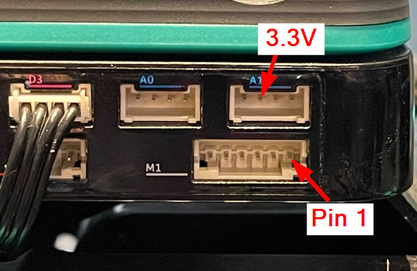
1: M+
2: M-
3: GND
4: 5V
5: Ch A
6: Ch B

One point of difference to note is the 5V power instead of 3.3V as is the specification for the motor you want to use - you should probably grab the 3.3V from the A1 pin above it and use that instead of the 5V on the motor port to be safe.

In terms of the RPM, our MCU that does the RPM control expects 52 pulses per rotation of the DC motor shaft - the magnet has 13 poles and we measure both the rising and falling signal of Ch A and Ch B so 13 * 2 * 2 = 52. The motor you linked says 4 per rotation - I’m not entirely sure if they mean 4 poles on the magnet which would be 16 pulses per rotation for our motor or whether they mean something else.

Essentially what this means is for one rotation of your DC motor shaft our MCU will receive 4 pulses, which it considers to be 4/52 of a rotation. Therefore it will take 13 real rotations of your motor for our MCU to consider it as a full rotation. This is why when you set an RPM it keeps going higher and higher until it reaches maximum - our MCU thinks it’s going much slower than it actually is.

You’ll have to play around with the MAX_DC_MOTOR_RPM value to account for this difference so that what our MCU expects is matched to what is given. This is an indirect way of achieving this but it should work - start by dividing your MAX_DC_MOTOR_RPM by 13 and see what the result is. In future we’ll consider making this configurable in software but for now this is the best solution I can think of