[Guide] pi-top[4] Power On by Pico

Well that was really simple to do, can be done from any micro controller to be honest or anything that can supply the logic high of 3.3v to the power switch pin.

@duwudi your idea works and here is how, thanks to @wil


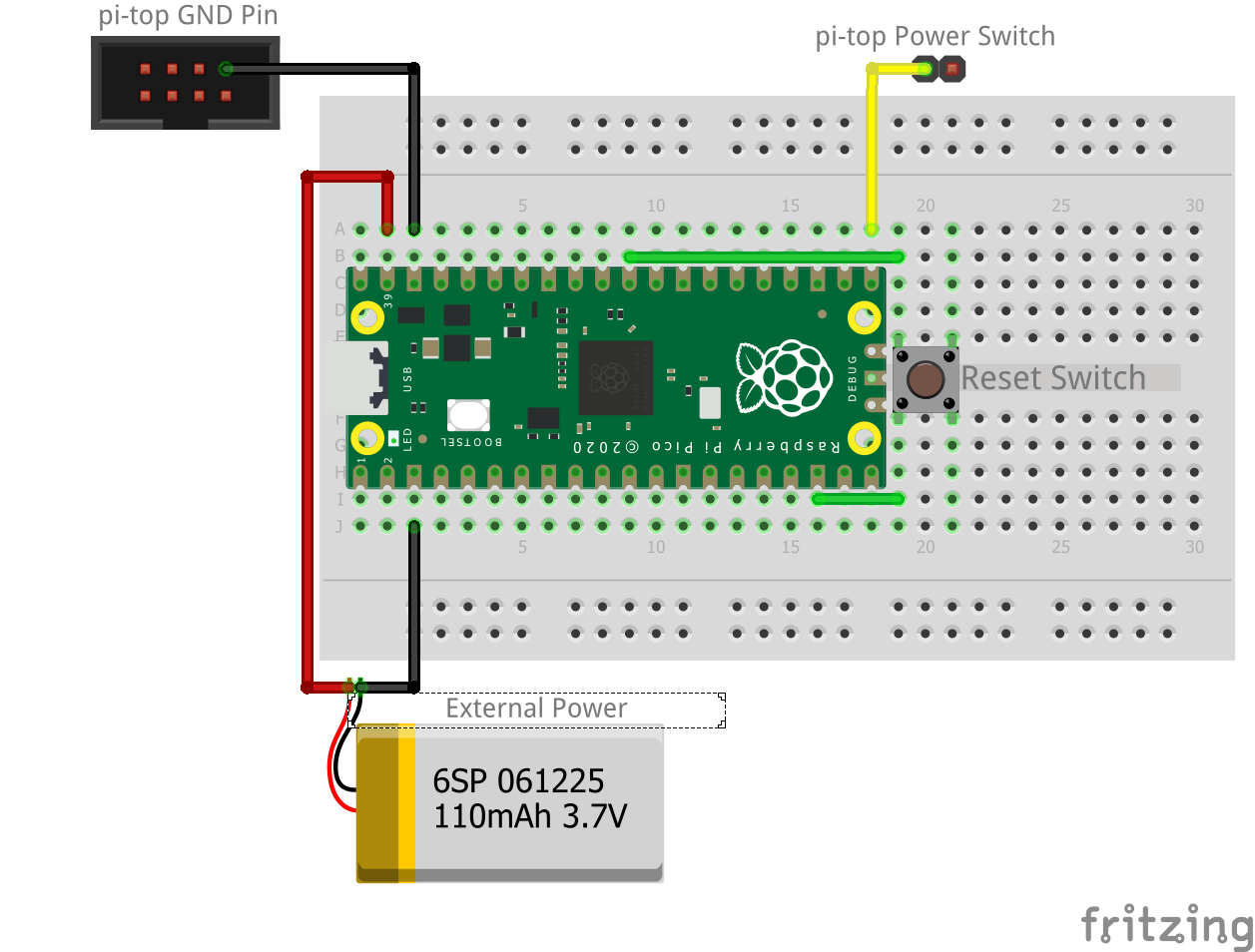
so, um, excuse the connectors, they are just for illustration purposes

  • Yellow Wire - Signal wire from the Raspberry Pi Pico This can be any non power/GND pin just as long as you program the correct pin
  • Black Wire (to top connector) - basically ground pin on the UI PCB, can be any ground pin to the pi-top
  • Green Wire - its just a reset switch to reset the Pico (RUN pin to GND)

Power can be from USB or VSYS, please ignore the battery, as its there as illustration to represent that power from an external source.

Program is extremely simple, and do remember that this is a test

from machine import Pin
import utime

#Pin to turn pi-top power on
wake_sw = Pin(16, Pin.OUT, Pin.PULL_DOWN)

#On board LED pin, used to show signal being sent
led = Pin(25, Pin.OUT)

# ensure that the power on pin is set to logic low of 0v
wake_sw.value(0)
power_on = False

while not power_on:
    # turn signal to Logic High 3.3V and turn LED on
    wake_sw.toggle()
    led.toggle()
    
    # Sleep for 1 second leaving Logic High 3V3 
    utime.sleep(1)
    
    # set power switch to Logic Low 0v and turn LED off
    wake_sw.toggle()
    led.toggle()

    power_on = True

Observations

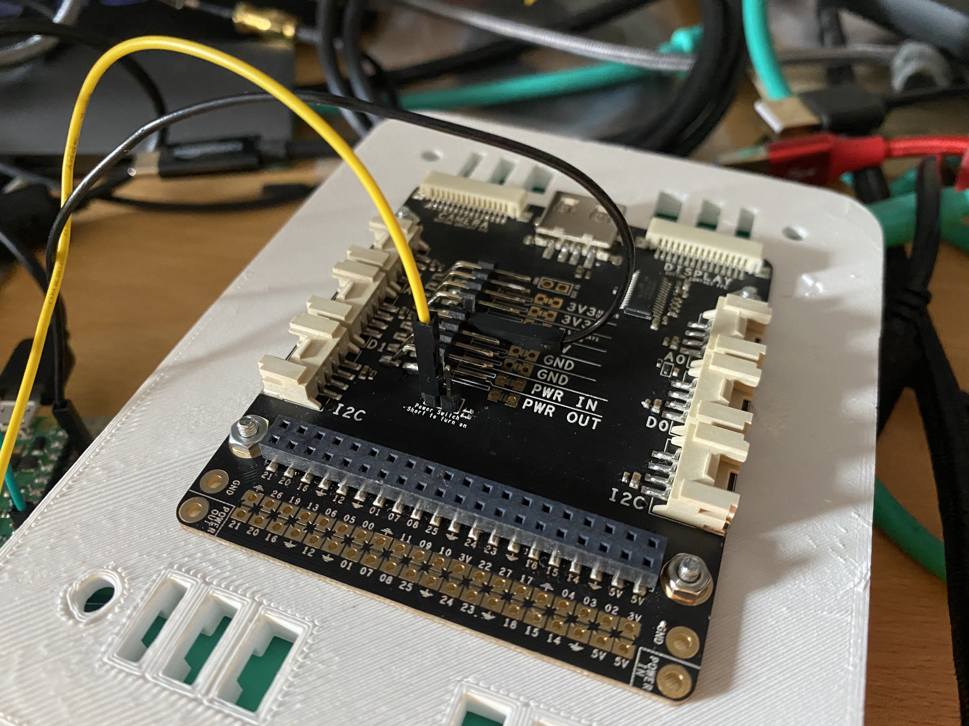
Powering the Pico directly from the UI PCB connected to the pi-top had an oddity. @wil maybe you can explain.

I had the signal wire (yellow wire) connected to the power switch on the UI PCB and when I connected the 3v3 Always on power to the VSYS pin of the Pico the pi-top powered on, could not power it off unless either the signal wire or 3v3 always on was disconnected. note, GND was not connected this created a latch keeping the power switch held on.

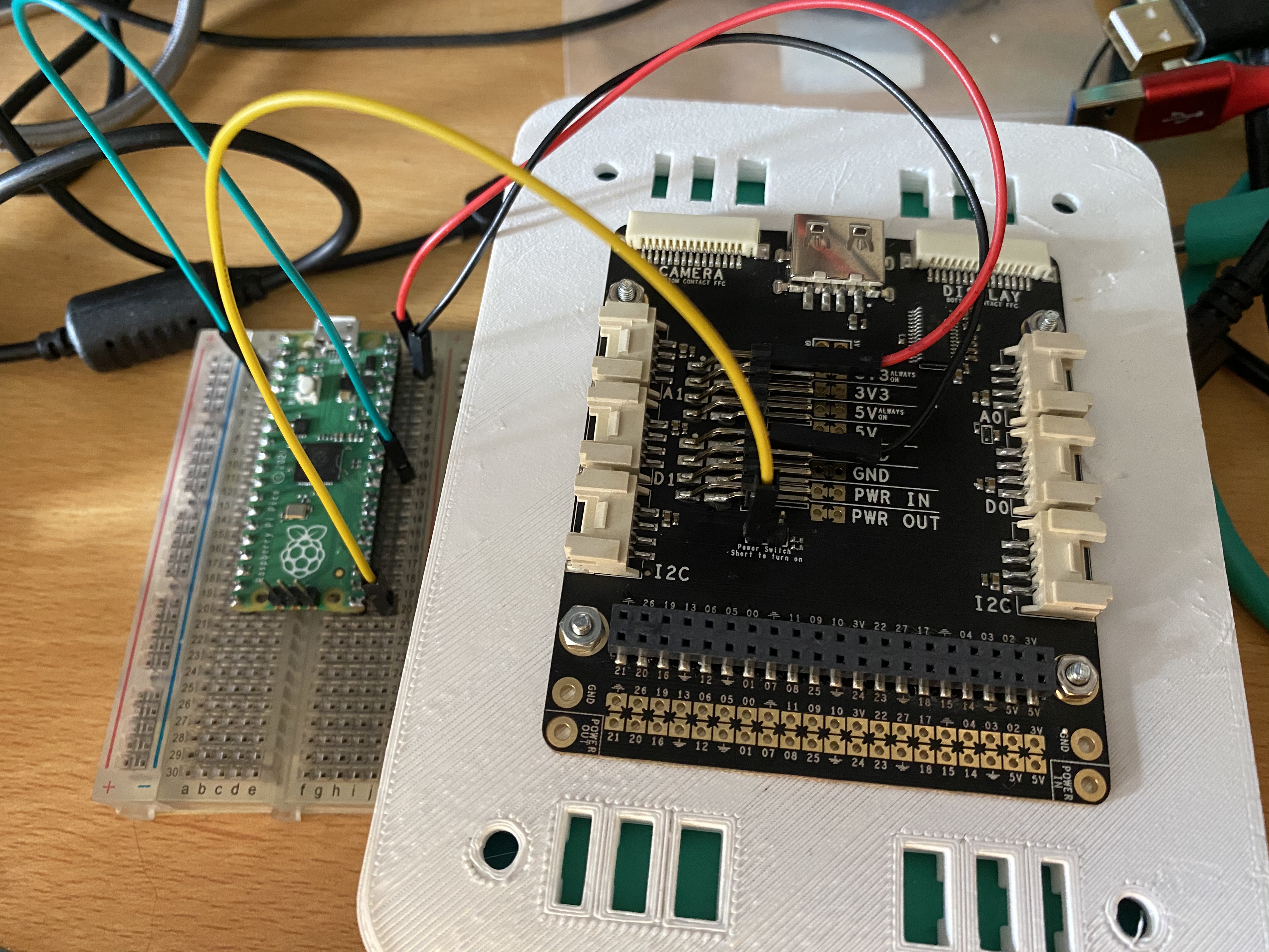
This made me power the Pico from USB from my Xavier NX as it was the closest device to the Pico. I have also tested taking a 3v3 and GND from the Xavier NX GPIO to GND and VSYS to the Pico and that also works.

0.3 Seconds and 0.5 seconds sleep timer was too short, 1 second is perfectly fine

@wil NOW its tested and works, nothing went boom or went up in smoke

This is the pico powered by Xavier NX GPIO to switch on the pi-top

3 Likes

Looks good! Although there may be different system grounds. Could you try powering it the with the UI PCB again and connect the pico ground to the UI PCB ground? They need to share common grounds and need to be on the right system ground to send signals properly. Battery ground and charger grounds often differ be an you have a battery protection IC that isolates the 2 parts. Devices as complex as a computer may have many grounds for different sections of the board to isolate boise and signals too :slight_smile:

1 Like

the ground was connected, either way i tried to power the pico from the pitop would just switch it on

1 Like

Hmmm, ok, I’ll have a look at it later tonight and see what results I get

oh its working, have to have power and GND connected before the signal wire then just remove the reset

Ahhh, gotcha. A lot of Macy’s use a diode to protect their pins and can actually power themselves through IO. This protection can power it and hold the pico in an unknown state until a reset can occur. Have you tried jumpering the reset pin?

image

The green wire I use for resetting RUN pin to GND and VSYS to 3V3 always on

Ah, I totally missed that. Sorry, just woke up :laughing:

No problem, at least we now know how to do this for our project :slight_smile: so useful testing done

1 Like

@CAProjects Great! This is the first project I know of that integrates a Pico with a pi-top [4] :+1: Do you have plans for the next steps?

1 step would be to detect if the pi-top is switched on, but this will be integrated into my weather station project. will also be looking into transferring data between pico and pitop as well

I also tweeted this mentioning the pitop team and raspberry pi :stuck_out_tongue:

Also @duwudi you can certanly take some credit for this, i did not know it was possible till you mentioned it :stuck_out_tongue:

Really looking forward to seeing you implement pico <-> pi-top comms, that’ll be so cool! Which comms peripheral you choose to use will tell us a lot about you:

Serial UART: I’m looking for something quick and easy
SPI: I have a lot of data to transfer
I2C: I hate myself

2 Likes

haha :rofl::rofl: :+1:

1 Like

Haha, I love it :joy::laughing:
Other things to note:
UART: interruptable transmissions.
SPI: need to spend some time here outside of an interrupt.
I²C: still hate myself haha

1 Like

what about SD card :stuck_out_tongue: i so have a micro SD card break out that i want to try get working on both the pico and raspberry pi so could, in theory, log the data to a daily file, when the pi turns on it grabs the file from the SD card and uploads to my NAS via FTP

I think the MCU has to communicate with the via SPI to most SD card adapters… but I haven’t done a whole lot. As far as 2 Masters and a slave type setup, I wouldn’t even know where to begin without researching it haha

So I got an Arduino Due, the main reason for the Due is the 3.3v logic output and not the standard 5v.

This gave me the idea to power on the pi-top with the Arduino Due and it worked

Important Note
Majority Arduino has a 5v logic output do not try this without using a logic converter to decrease the logic voltage. Not doing so will fry your pi-top

I attempted this with checking with an Arduino geek friend before doing this. With talking to him about requirements, he told me to get the Due

1 Like