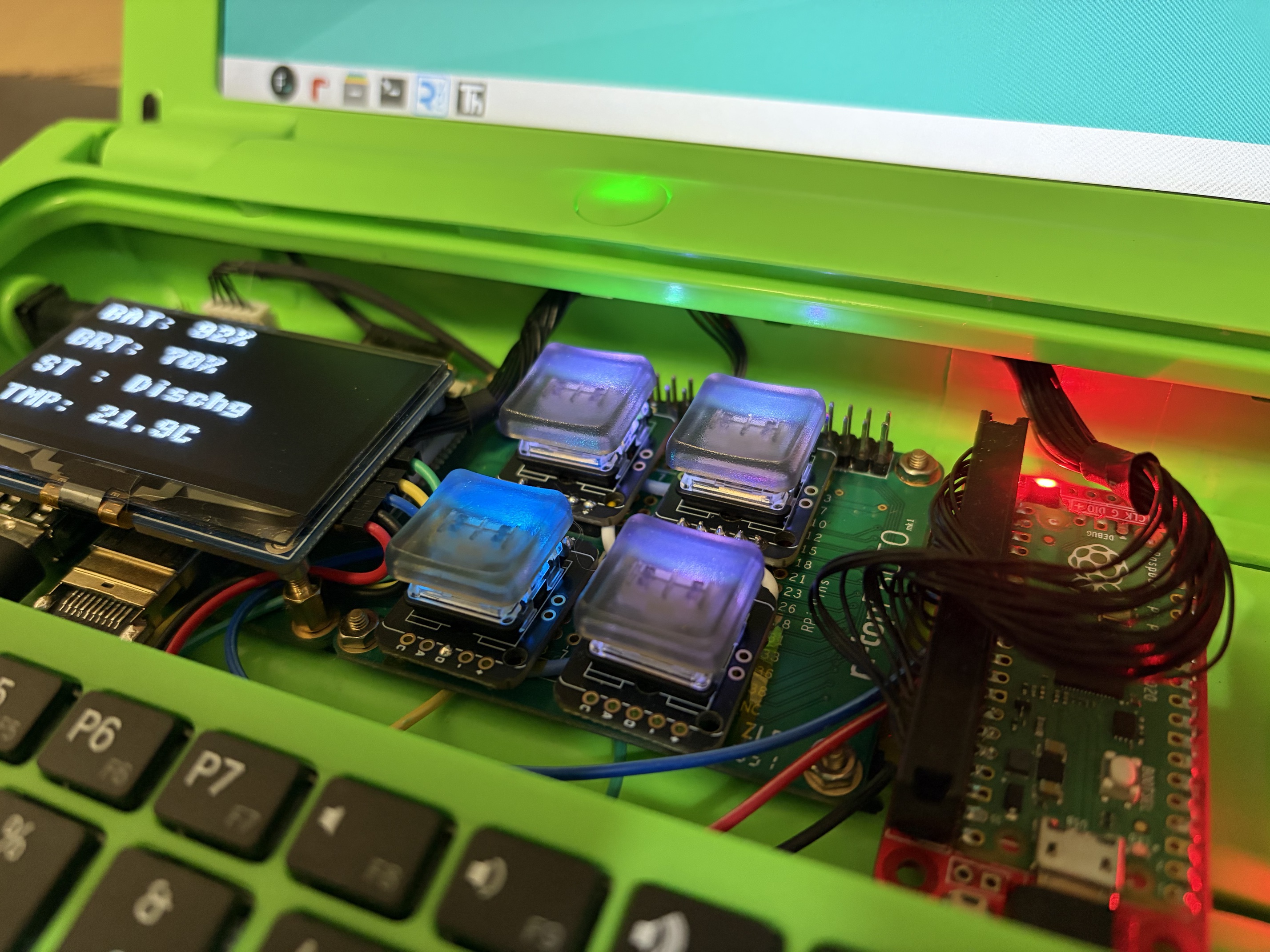
Maybe once I have a fully working concept working; getting there though, got an OLED working with it now:

Wiring is a mess here but the core concept is working solidly off the Pico (RP2040).

Maybe once I have a fully working concept working; getting there though, got an OLED working with it now:
Wiring is a mess here but the core concept is working solidly off the Pico (RP2040).
Found some more time to work on this little project. Have now updated the buttons to both a four button layout: Brightness Up, Brightness Down, Blank/Unblank the screen and Page to toggle the OLED display output. I have also soldered down the buttons onto a PROTO board, along with the OLED connections so now all I need to do is connect the Pico to the GPIO pins, plug in the PROTO board and it’s all working!
I’ll add this new version of the script to GitHub later and a little write up so if anyone else wanted to either build this or use the code to make something similar (different screen, more or less buttons, etc) they’re welcome.
Otherwise very happy with how to worked out - some soldering mistakes in regards to blocking paths I had planned to use but otherwise got it all working nicely.
Now this is all working, I will be looking to switch out the Pi4 for a Pi5.
Sweet! 
Looking forward to reading the write up and seeing where you take this next! Not on topic for this thread but would you ever consider trying SBCs other than the RaspberryPi 5?
Thanks, will try to get the new code and write up down in the next couple of days.
Regarding getting another SBC over the Pi5, it depends on whether you mean using the Pico to communicate with the Hub and a different SBC connected to the HDMI & keyboard/mouse USB or having a single SBC only connected to the Hub to do both communication & display + keyboard/mouse, as the former should be fine to go as it is, but the latter may be a little more complicated.
In my current state with the Pico, I don’t foresee any reason why I couldn’t connect any HDMI device to the Hub and output that to the Pi-Top screen (will test this anyway), so should work fine.
To have another SBC controlling the Hub however would potentially be viable depending on the board’s GPIO configuration as you only need at least 2x I2C pins & 4x SPI pins, but it’s then a matter on how to display this information (battery stats) and control the screen; with physical buttons and a separate screen could work fine and I have considered swapping out the full sized Pico for a smaller Pico and other smaller microcontrollers that could do this.
But to have just a SBC control the hub & output on the main display and utilising the keyboard for screen brightness would be very tricky but I’m sure someone with the original Pi-Top code and the time to chip away at this could make something work; would be a little outside of my current knowledge window but could be fun to learn…
I’ll try another HDMI device or SBC connected to the Hub in my current configuration and see.
Just curious to see if there has been any progress on this as I have been following along.
Also the aforementioned Tindie Pi hat is not being sold at the moment. Would this adapter board work just as well or do you know of another place or seller for it? https://www.adafruit.com/product/6249
Hey Verault,
So the project is complete and working with both a simple button matrix soldered directly to a PROTO board & OLED display. In my example I am using the Red Robotics Pico to Pi board, as seen below:
I don’t envision any reason why it wouldn’t work with this board, the only main difference between the two are the pinouts are different between the two, but should be trivial to correct. I did note this on my GitHub page, but also had ordered a Hard Stuff Pico to Pi hat so can test this myself, however the buttons I’ve wired to the PROTO board won’t work with this version so may need to make a new board of buttons.
Ive managed to upgrade my Pitop V1 to a pi5 and get the brightness and volume buttons working along with audio out via my PitopV2 speakers. It took a couple of afternoons work but I’ve asked MS Copilot to summarise the process for anyone else looking to tackle this further down the line as it took quite some work! As usual with AI summaries its not the clearest overview but you should get the idea!
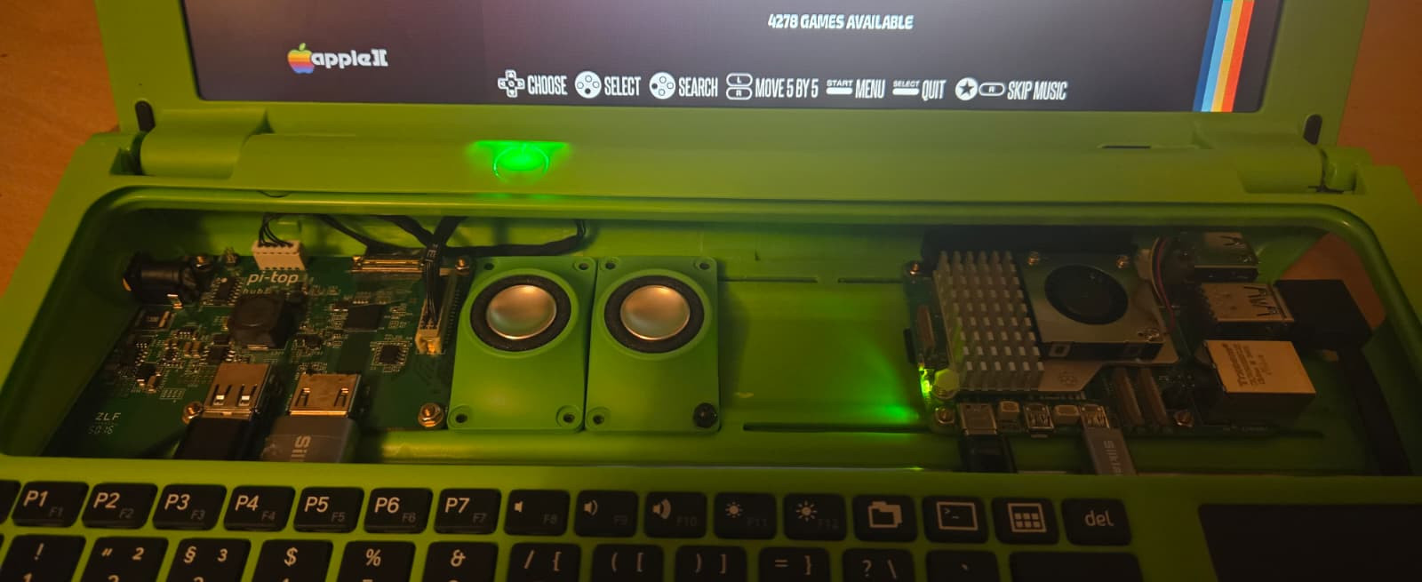
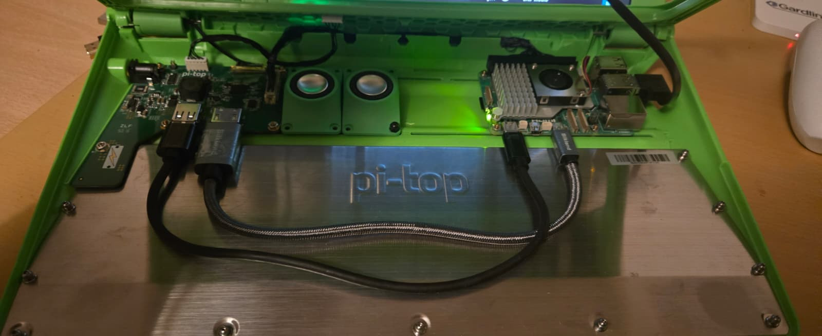
Hardware wise, I’m powering the Pi5 directly off the v1 Hub USB with a 30cm USB - USB C cable of good quality and it seems to be coping fine so far. Hdmi wise, again a 30cm HDMI to micro HDMI cable works fine and both were about £15 in total off Amazon.
Software hacking Process as follows:
Getting pi-top [4] Speaker Board, Volume Buttons & Brightness Buttons Working on a pi-top V1 Running Recalbox (Raspberry Pi CM5)
After a lot of investigation, I finally managed to get the original pi-top V1 hardware controls working correctly with a Raspberry Pi CM5 running Recalbox inside a pi-top V1.
This guide covers:
 pi-top V2 speaker board communication Brightness control over SPI Hardware brightness buttons Hardware volume buttons Automatic startup integration
The pi-top peripheral board connects via:
Out of the box:
The key challenge is communicating with the onboard microcontroller via SPI.
Step 1 - Enable SPI
Remount /boot as writable if necessary:
Shell
mount -o remount,rw /boot
Edit:
Shell
/boot/recalbox-user-config.txt
Add:
Shell
dtparam=spi=on
Reboot.
Verify:
Shell
ls /dev/spidev*
Expected:
Shell
/dev/spidev0.0
/dev/spidev0.1
# Step 2 - Verify SPI Communication
The pi-top control board is attached to:
Shell
/dev/spidev0.1
A simple SPI transfer test:
Python
import os
import fcntl
import struct
SPI_IOC_MESSAGE_1 = 0x40206b00
fd = os.open("/dev/spidev0.1", os.O_RDWR)
tx = bytes([0x50])
buf = bytearray(1)
import ctypes
tx_buf = ctypes.create_string_buffer(tx)
rx_buf = ctypes.create_string_buffer(1)
msg = struct.pack(
“QQIIHBBI”,
ctypes.addressof(tx_buf),
ctypes.addressof(rx_buf),
1,
500000,
0,
8,
0,
0
)
fcntl.ioctl(fd, SPI_IOC_MESSAGE_1, msg)
print(hex(rx_buf[0]))
os.close(fd)
A successful response confirms communication with the controller.
# Step 3 - Brightness Control Script
Create:
Shell
/recalbox/share/system/brightness.py
Example:
Python
#!/usr/bin/env python3
import os
import fcntl
import struct
import ctypes
import sys
SPI_IOC_MESSAGE_1 = 0x40206b00
LEVEL = int(sys.argv[1])
LEVEL = max(0, min(10, LEVEL))
tx = bytes([0x20 | LEVEL])
fd = os.open("/dev/spidev0.1", os.O_RDWR)
tx_buf = ctypes.create_string_buffer(tx)
rx_buf = ctypes.create_string_buffer(1)
msg = struct.pack(
“QQIIHBBI”,
ctypes.addressof(tx_buf),
ctypes.addressof(rx_buf),
1,
500000,
0,
8,
0,
0
)
fcntl.ioctl(fd, SPI_IOC_MESSAGE_1, msg)
os.close(fd)
Usage:
Shell
python3 brightness.py 5
Set brightness level 0-10.
# Step 4 - Identify Button Input Device
List input devices:
Shell
for e in /dev/input/event*; do
echo “=== $e ===”
cat /sys/class/input/${e##*/}/device/name
done
On my system the pi-top controls appeared as:
Plain Text
PT Global Button Controller
Using:
Shell
evtest
showed button events being generated correctly.
For me this was:
Shell
/dev/input/event2
Your event number may differ.
Create:
Shell
/recalbox/share/system/custom.sh
Example logic:
Shell
#!/bin/bash
python3 /recalbox/share/system/pitop_buttons.py &
Create a Python daemon that:
/dev/input/event2
Shell
brightness.py
with updated values.
The same button controller reports:
Simply map them to ALSA:
Shell
amixer set Master 5%+
and
Shell
amixer set Master 5%-
inside your button handler.
Example:
Python
import os
os.system(“amixer set Master 5%+”)
or
Python
os.system(“amixer set Master 5%-”)
Recalbox executes:
Shell
/recalbox/share/system/custom.sh
during boot.
Make it executable:
Shell
chmod +x /recalbox/share/system/custom.sh
Verify:
Shell
ls -l /recalbox/share/system/custom.sh
After implementing the above:
| Feature | Status |
|---|---|
| pi-top speaker board detected | |
| SPI communication established | |
| Brightness control working | |
| Brightness buttons working | |
| Volume buttons working | |
| Automatic startup | |
| Recalbox integration | |
The next area to investigate is battery monitoring.
The embedded controller appears to expose additional information over SPI and it may be possible to retrieve:
If anyone has documentation for the original pi-top V1 controller protocol, I’d be very interested in collaborating.
Many thanks to the Copilot-assisted debugging session that helped trace the SPI device mappings, button controller events, and startup integration. Hopefully this saves someone else many hours of reverse engineering!
Feel free to adapt and improve this guide as more of the pi-top hardware protocol becomes understood.
Very cool and comprehensive write up. But could you post some photos of your setup?
Some pics as requested, struggling with my newbie limit of 3 posts per topic and only 1 pic per post!
Another picture below, just waiting for a thinner HDMI cable to arrive before I seal it up, that was just one I had laying around for testing purposes however its too thick for this application.
I’m running dual speakers but haven’t yet found a solution to get stereo working, not sure its even possible using the V2 speakers with the V1 hub but I’ll have another look when I have time.