PMA diagram doc mistake

Just spotted a little mistake on the PMA diagram :smile:

image

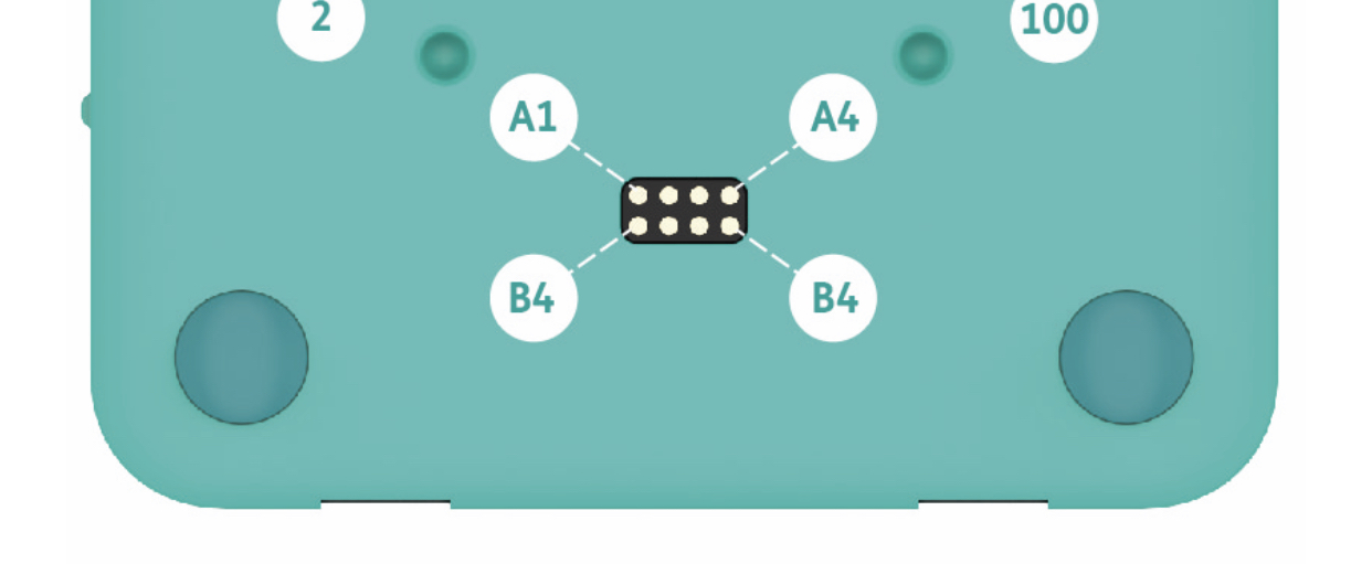
Think the left B4 should be a B1 :stuck_out_tongue:

Just a little question about the A1-4 and B1-4 pads, are these for anything specific or is it some dev thing? I know they are labled just wondered if they are for a specific use. Looking at the diagram, looks like SPI and UART if I remember correctly of the top of my head

2 Likes

@CAProjects - It’s nice to B1 of those guys that catches mistakes B4 it gets people confused. hahaha

4 Likes

OMG hahahaha nice play there :stuck_out_tongue:

2 Likes

We’d make a good team, I tend to do the same thing. :wink:

https://forum.pi-top.com/t/robots-kit-info-on-home-page/430

1 Like

It looks like the programming port, possibly for the pi-top firmware or microcontroller(s) inside. This is speculation though. I image this is probably proprietary… @duwudi will we every get a description on these? Haha

@Tom-B bwahhahaha! :rofl::rofl::rofl:

@Tom-B hahahaha genius! Love the way your mind works :laughing:

@CAProjects the pogo pads have I2C, UART, 5V and 3.3V I believe. I’ve asked @RezIN to update that article and fix the errors in it so once he’s done that he’ll tell you here. We added these so that people could make simpler low-cost plates that didn’t need the big 100 pin connector, all you’d need is a PCB with some off the shelf pogo pins which would reduce the cost and size. I actually used it once when I designed and built a pi-top [4] Drone, the drone itself was powered by a separate high-discharge LiPo battery so all I needed was a common ground and a UART connection to the flight controller.