
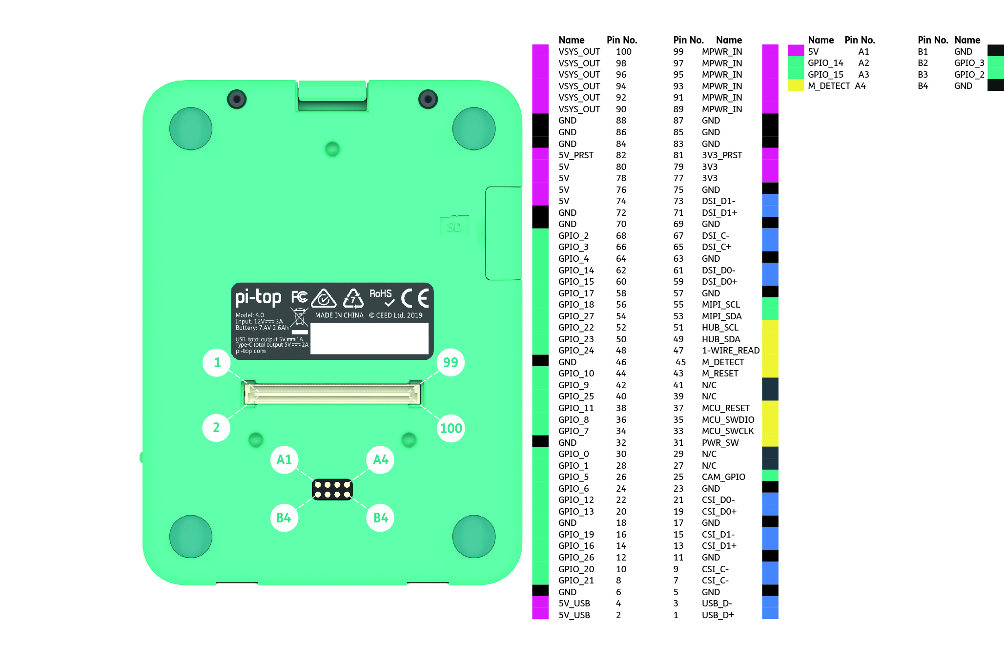
Here’s the pinout for the PMA Connector and the Pogo Pins. You may hear us sometimes call it the Modular Connector. This is Modular Connector is doing a lot of work and has a whole host of connections running through it. Just follow the key and you should be okay. The Plug is mounted inside the pi-top [4] but all our plates use the receptacle.
It’s a 100 pin connector (50x2) with a 0.80 mm pitch. The manufacturer is Amphenol and the recpt part number is 10144517-10XXXXXX while the plug part number is 10144518-10XXXXXX.
We recommend downloading the image so you can see all the definitions!
| Power Pins | ||||
|---|---|---|---|---|
| Name | Function | Voltage (Volts) | Max Current (Amps) | Descriptions |
| VSYS_OUT | Power Out | 6.4 - 8, 12, 15 | 3 | Outputs System Voltage. If using Battery power then 6.4 - 8.4Volts. If using USB-C Power 12 or 15 Volts. Max output is 3A. Fuse protected |
| MPWR_IN | Power In | 9 - 14 | 3 | Input to System Voltage. Lower priority to USB-C PSU. Higher priority to battery power. Can be used to charge battery pack. Fuse Protected |
| 5V_USB | Power Out | 5 | 0.6 | Direct from Raspberry Pi USB Port |
| 5V_PRST | Power Out | 5 | 0.75 | Available when device is powered off. Turns off when battery power dips below 5%. Fuse protected |
| 5V | Power Out | 5 | 3.5 | Shares same source as 5V from 40pin connector and pogo pins but separate to 5V supplied to Raspberry Pi. Fuse protected |
| 3V3_PRST | Power Out | 3.3 | 0.15 | Available when device is powered off. Turns off when battery power dips below 5%. Fuse Protected |
| 3V3 | Power Out | 3.3 | 1.5 | Shares same source as 3V3 from 40pin connector. Fuse protected |
| Data Pins | ||
|---|---|---|
| Name | Function | Description |
| GPIO_XX | I/O | GPIOs tied directly to Raspberry Pi. ESD Protected. Direct connection between the 40pin connector and the PMA Connector |
| MCU_RESET | Input | External Reset to pi-topHub MCU. (Connect to GND to reset) |
| MCU_SWDIO | I/O | MCU Serial Wire Data Input/Output |
| MCU_SWCLK | I/O | MCU Serial Data Clock |
| PWR_SW | Input | Tied to device power switch. High to turn on. Logic High @ 2.2V |
| USB_DX | Data | USB data pair from USB-Hub Controller on pi-top Hub |
| DSI_XX | Data | Display Serial Interface from Raspberry Pi |
| CSI_XX | Data | Camera Serial Interface from Raspberry Pi |
| MIPI_SXX | I2C | MIPI I2C from Camera/Display Serial Interface from Raspberry Pi |
All pins marked N/C are not electrically connected.
