
@wil: Hi, thanks a lot for the reply and reconfirming, I will need to have a careful look into this during the weekend, I just wanted to rule out the usb-to-uart. I simply love the board and if I can’t find a solution with the current setup, I might go down the route of using the gps via usb, it wouldn’t look so packed together but it is what it is😂. Thanks again for the fantastic work with this board,it just opens up so so many possibilities.
4 Likes
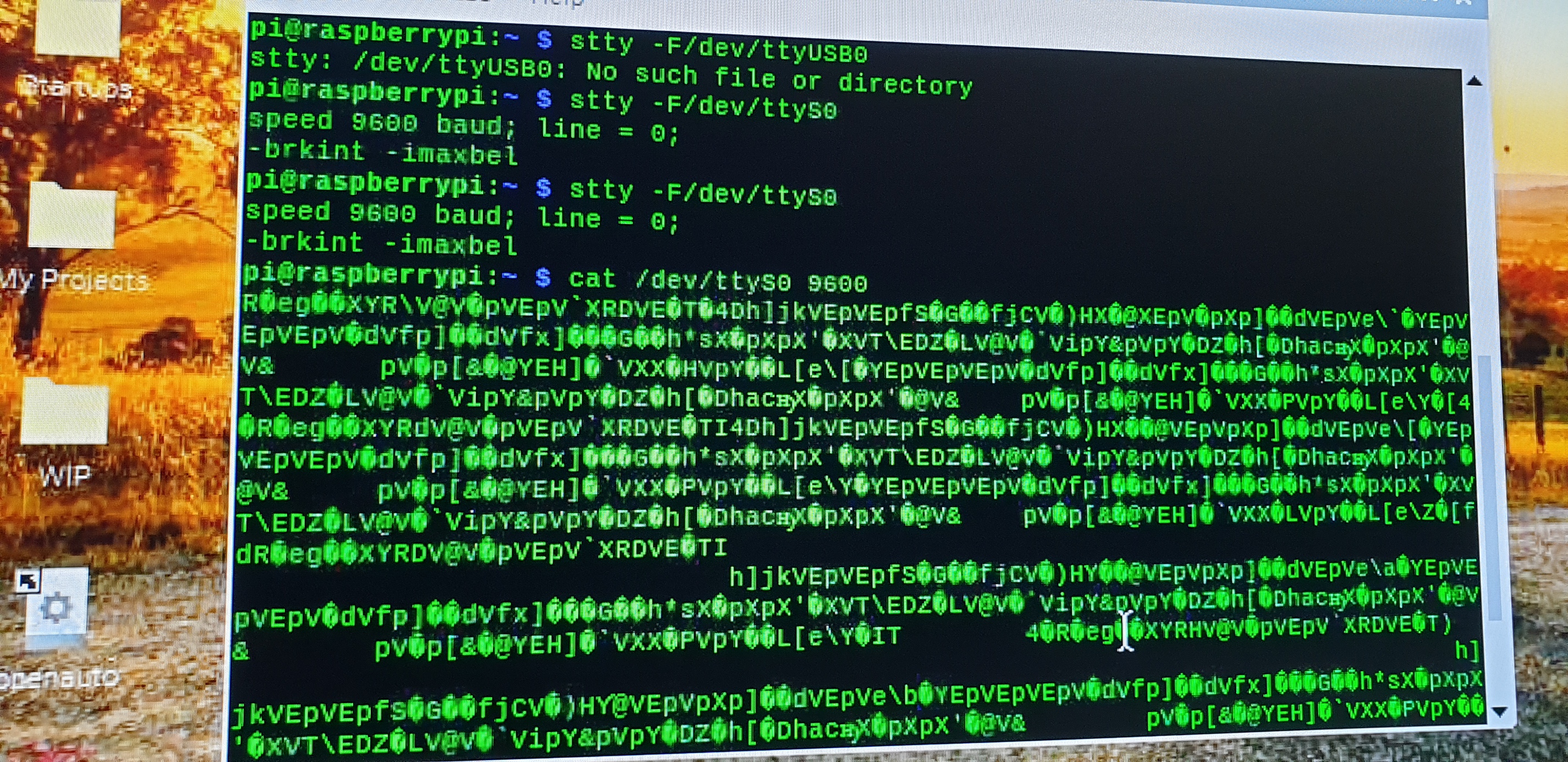
@CAProjects, thanks for looking into this. The baudrate doesn’t seem to be the issue, I have tried before to add the baudrate in config.txt. Have also run the code you suggested and I am getting the following:
1 Like
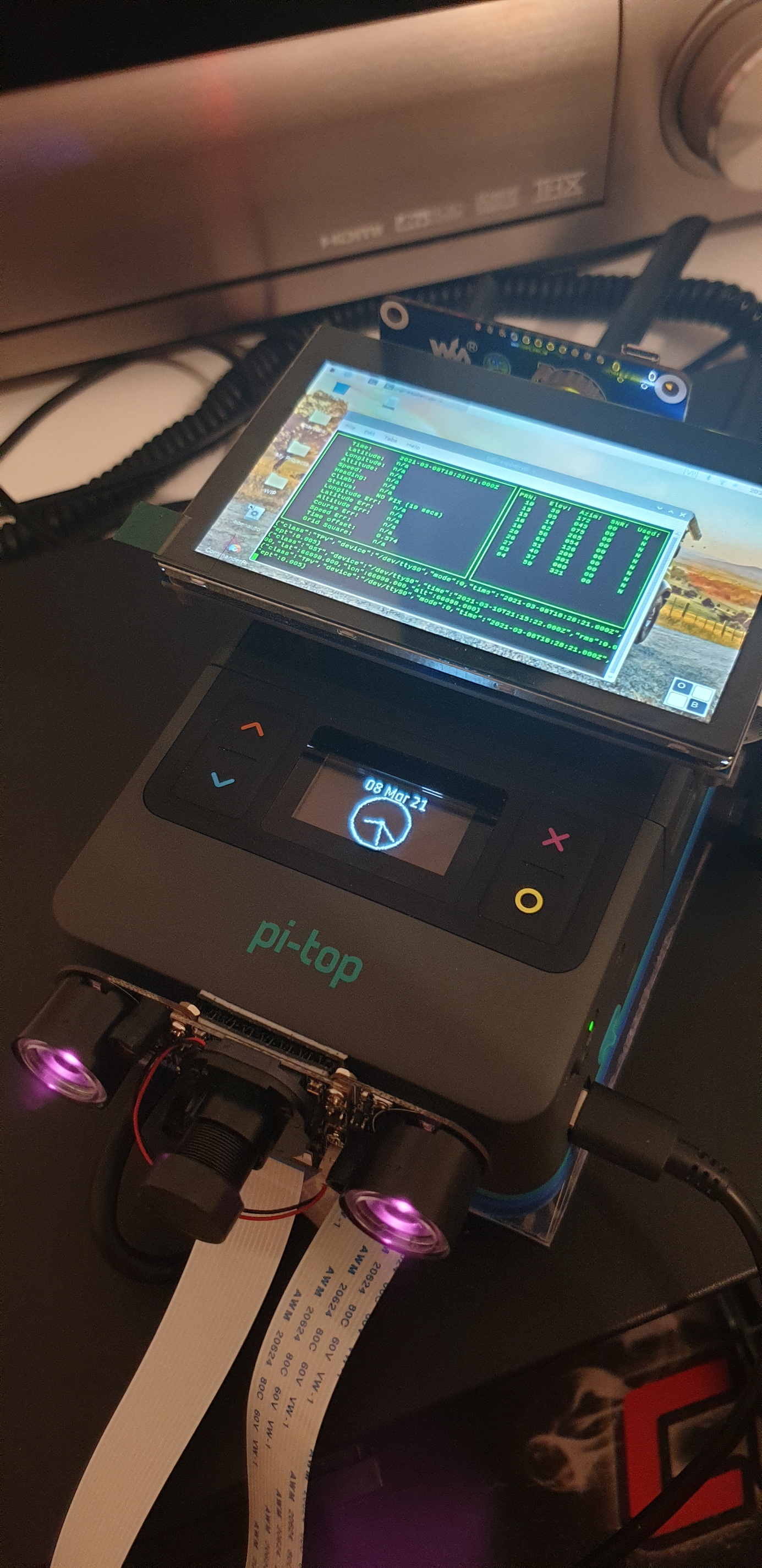
Guys, I found the problem, it seems the overclock I did a was culprit. Once I went back to the defaults everything is working.  . Now both gps and wifi adapter are working.
3 Likes
That’s very curious… what were you overclocked to? Generally, overclocks shouldnt change board rate as the timers are set by hardware. The raspberry pi knows that its counting faster than it was before.
@duwudi bug report possibly?
I was running arm_freq=2000, gpu_freq=600 and over_voltage=6. For the overclock I was a bit lazy and did it with commanderpi. Don’t know if this matters. But I went back in /boot/config.txt and uncommented these lines and gps was working again. It was driving me crazy since I did not know what was going on. My fault here was that, again was very lazy😂, copied the config.txt since I didn’t want to put everything in for the new build and connected the bottom plate. This lead me to believe in error that the universal pcb has something to do with it, when all along it was the OC.
1 Like
Hey, if it works, roll with it! Overclocking is pretty simple on the pi though… I’ll test the baud rate in a little while and see if I have issues too. I’m currently running 2200 cpu and 725 gpu with +8 on voltage. Now I’m curious haha
@Supernovali: Hahahaha, you went pretty much full speed with those😂. Would be interesting to see if your setup is doing the same. Pls post the output of cat/dev/ttyS0 to see if you get those funny looking characters😁.
1 Like
@Luis do this
apply the over lock and add core_freq=250 to /boot/config.txt
No big report needed I completely forgot about what I mentioned above. If you google gps and raspberry pi it’s always said to add the line above. Wasn’t till @Luis mentioned overclock I remembered core_freq setting
2 Likes
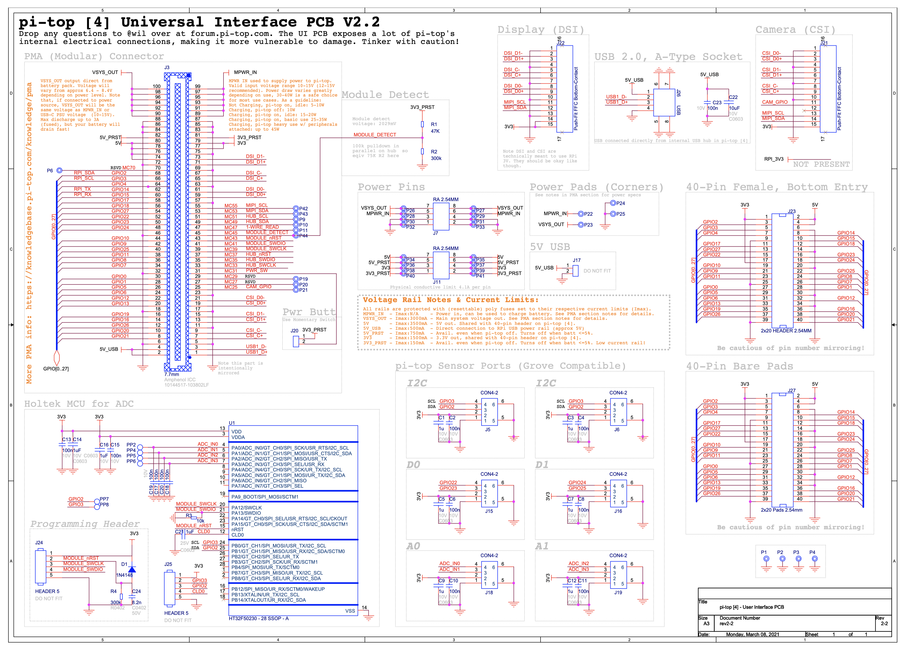
Okay folks - I’ll host this as a PDF somewhere sensible soon, but as a sneak-preview here’s the full schematic of the UI PCB. To my knowledge this is the first time we’ve shared one of our internal schematics - brave new world! But a very exciting one too, open source is definitely the way to go. Let me know if you spot any problems - annotated board image to follow soon too!
4 Likes
Oh hahaha yeah, core frequency might do it haha
And @wil, very nice and clean schematic! I love it! What program are you using to generate this? Looks better than KiCad
1 Like
OrCAD Capture and Allegro are our schematic/layout weapons of choice at pi-top 
2 Likes
What are you using to interface the GPS? I don’t have a gps module but I can write a quick program to get an Arduino to echo serial and check out my ttyS0. Are you using GPIO serial or USB Serial?
@wil, I’m going to have to check those out! 
1 Like
@Supernovali: I’m using GPIO serial.
@CAProjects: thanks for the suggestion,will try out the core_freq=250 and keep the overclock.
1 Like
@wil thanks for this, much appreciated. Whilst I have never looked at diagrams such as these it’s a learning experience
1 Like
Just got mine today. But I just reinstalled Raspbian and updated everything… And now I have to vnc in. Can’t get the hdmi-2 port running now blah. Gonna start a new thread
@CAProjects: this seemed to do the trick, got the OC and GPS working, should core_freq=250 report CPU min = 250Mhz? If yes, in commanderpi I am still getting 600🤔
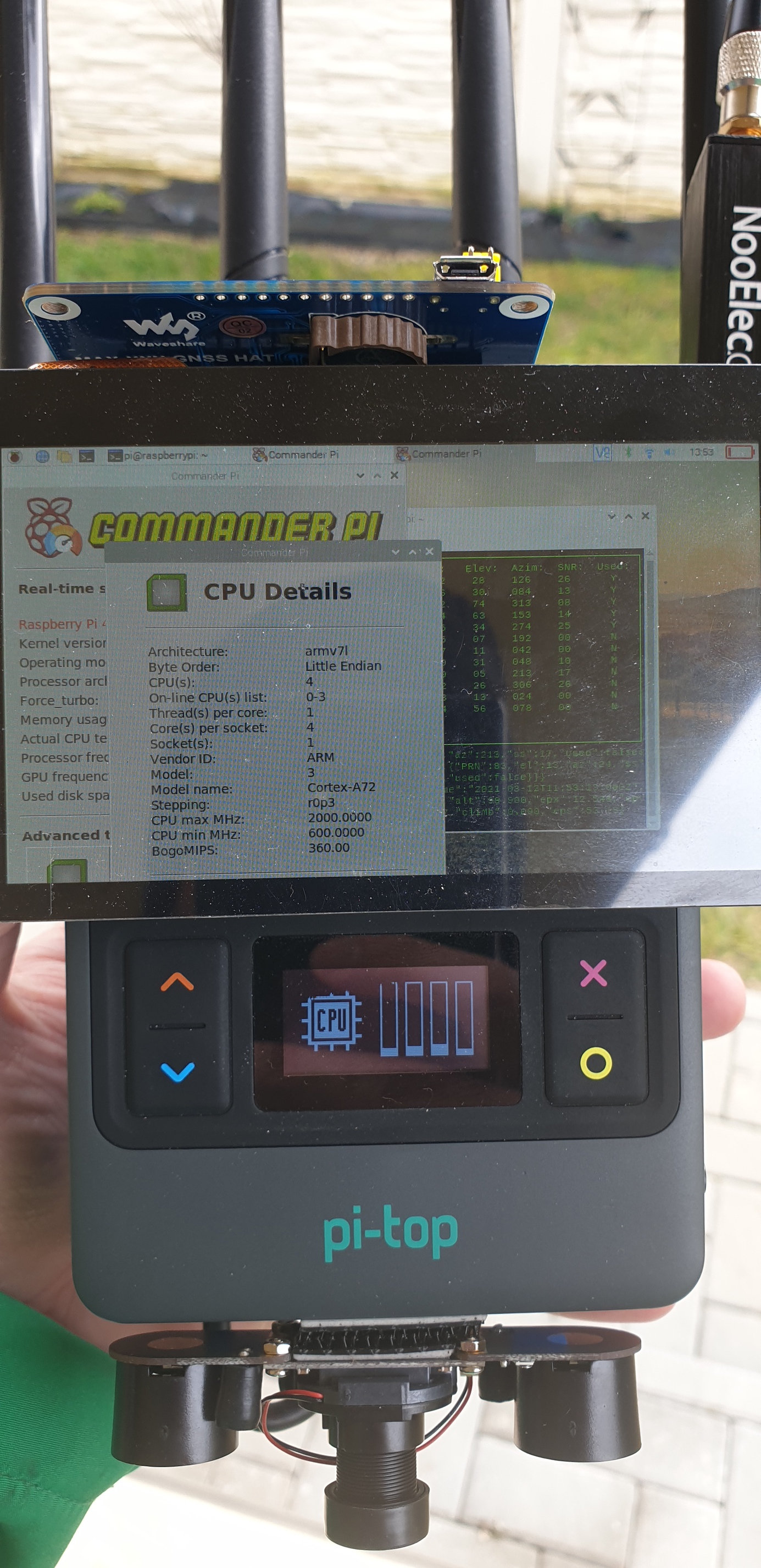
UART uses a fixed VPU core clock frequency and because its linked to the core clock when the CPU clock frequency changes the UART baudrate will also change, core_freq=250 will keep it running at 250. This does not show up on pi commander as its not info they display.
Basically this information comes from the Raspberry Pi documentation. I thought it was a setting the community come up with when in fact, Raspberry Pi say to do this in the docs.
2 Likes
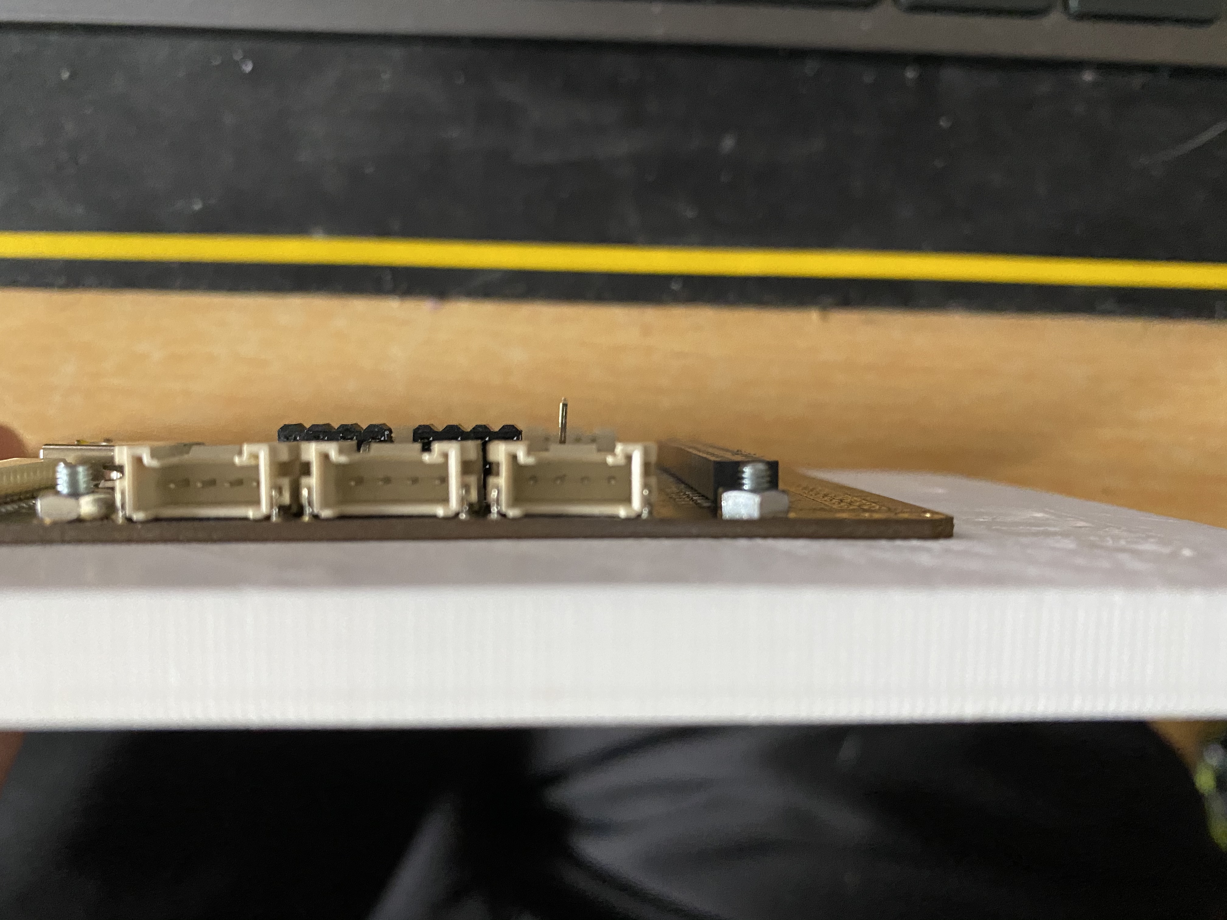
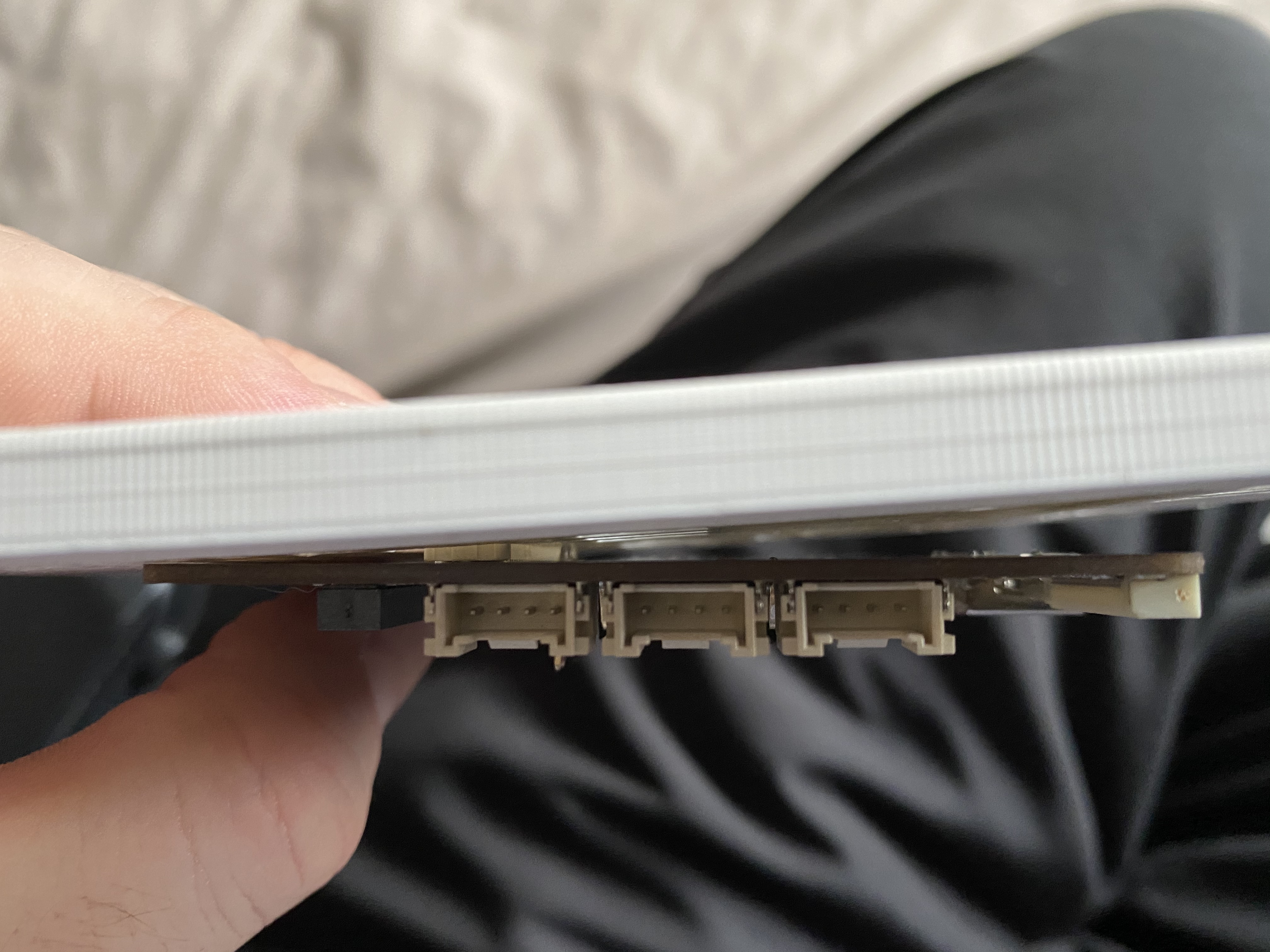
@wil some more feedback for you, with a backplate for the UI PCB, 1 thing you may want to cincider is if soldering to the UIPCB such as headers, or wires or what ever, you would need ot have space the other side of the board. as the coard came, it sat fluch with the dock plate
so i have added a 2 pin header, you guessed it, for the pi-top power switch a little hack away with a craft knife and its all sits perfect. i didnt pick up on this till now as i did not solder anything to the board.
Here is a before and after
1 Like
Great point - I hadn’t even considered this! That’s just the kind of feedback I’m looking for, I’ll make a note to change that for the next iteration. Thanks!
1 Like