Universal Interface PCB

With @wil coming up with the Universal Interface PCB and got my hands on one to play around with/test and offer feedback. I am sure others have one too, so lets discuss it here

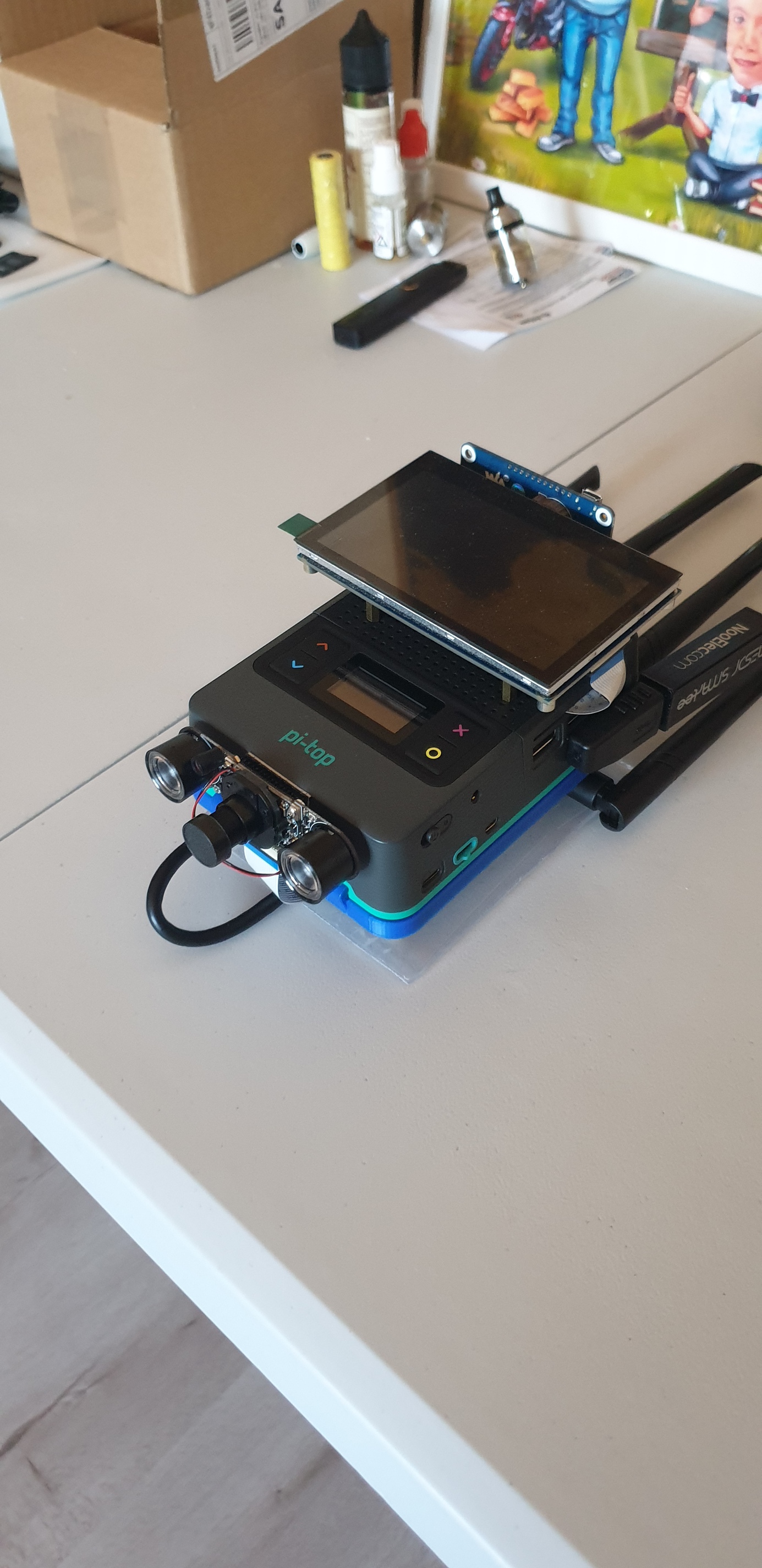
So I got one and got myself some Grove sensors and put this together.

Hardware

  • Grove 16x2 LCD - plugged into I2C
  • Grove DHT11 - Plugged into D1
  • pi-top button = plugged into D0
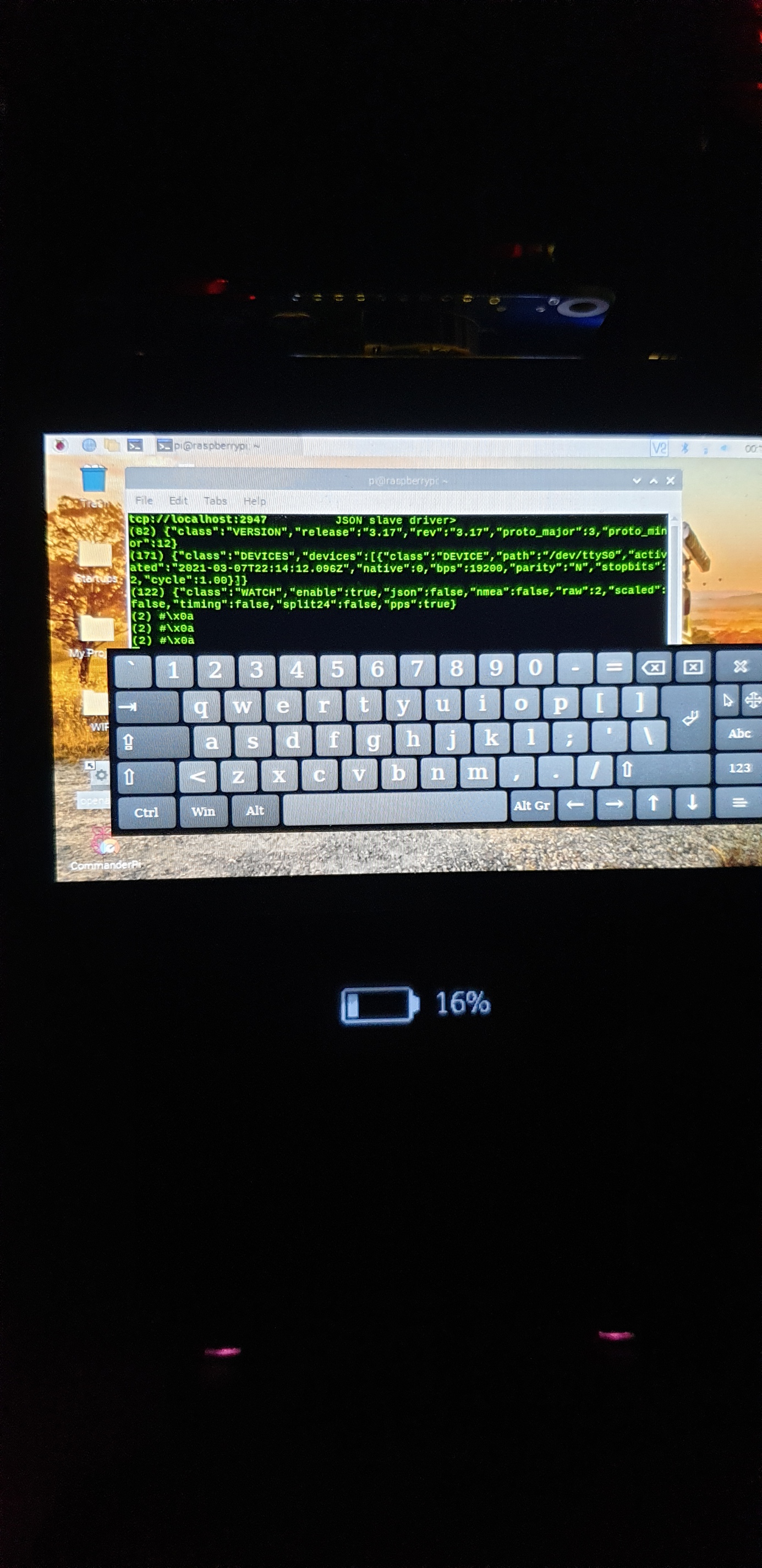
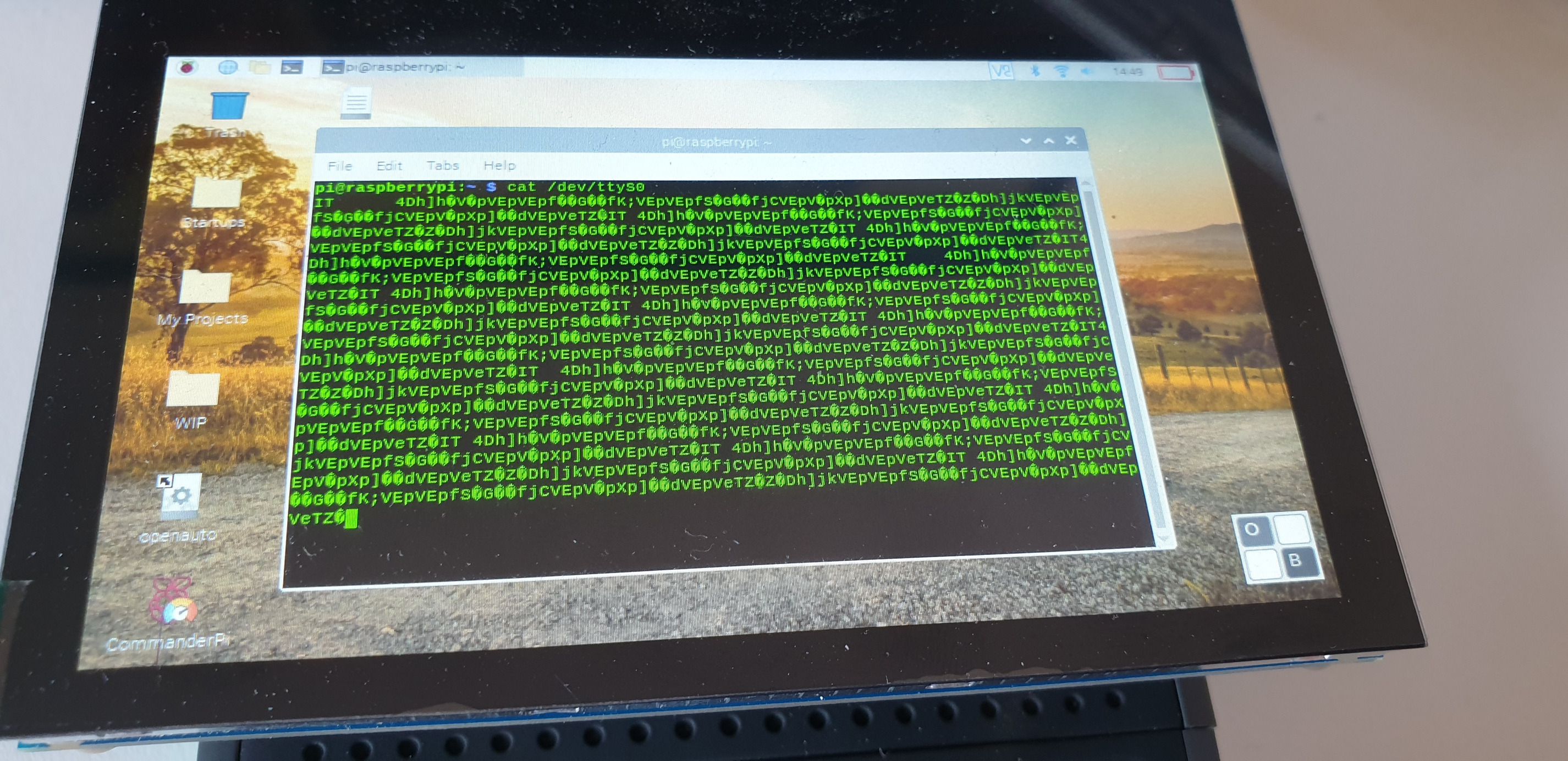
  • Adafruit Ultimate GPS Breakout v3 - Plugged into GPIO

I did use some Grove Libraries because I don’t really know I2C and wanted to get something working

It’s nothing special, set it up to show some text and push a button to change the text or display sensor data. Sadly I really do not know how to use the Analogue or I would have used that too. hoping @wil can help out here or let us know some documentation or something, I tried using the pi-top SDK but it would not let me as I needed the foundation plate plugged in

just wondering a few things

  • The USB socket, What’s that for? is it just power in or out?
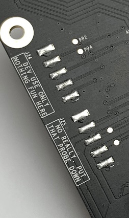
  • The pins in the middle, is that for power in and out? like the pads next to them
  • How do I get A0 and A1 working exactly?

Overall I like the board and looking to do more with it, think my plan is to do a long term project with it to see how it works for more than a short demo or testing but I think it will be ok.

What to I have planned for the board? well i would like to make a Personal Weather Station and integrate it to the Weather Channel personal weather station network, something like this bit incorporate solar and run from battery

https://projects.raspberrypi.org/en/projects/build-your-own-weather-station

5 Likes

@CAProjects this is great, nice work getting all this going so quickly! :+1:

I’ll let @wil respond on the pin definitions for power etc, maybe he can provide an annotated diagram for all of the functions on the PCB.

The USB socket is a normal USB 2.0, it’s got data and power.

A0 and A1 should be compatible with Grove’s analogue sensor libraries I believe as we use the same registers and interface as them on the Foundation Plate. Can you send the errors you get about the Foundation Plate not being attached? We might need to make that a warning instead of an error in future.

I tried the Grove lib for an air quality sensor but I got an error saying that the Grove hat could not be found, but it does seem that the Grove libs are all over the place instead of all in one place and easy to use

Ahhh, I can’t wait to get mine now too!

@CAProjects This is great, I’m so excited to see you’ve got going with it so quickly! :star_struck:

A few quick answers to your questions:

Most importantly, in my hurry to send these out I forgot to tell you that on these prototype boards, that analogue function does not exist, despite having the analogue port.
The reason for this is simply that this functionality needs that little on-board microcontroller to be programmed, and only after they’d sent me them from China did I realise/remember that I don’t have the programming tool here required to do that myself. So even though the hardware is there, the firmware is not :man_facepalming: Sorry about that, I’m sure I would have saved you some time had I remembered to warn you!

For the record you were on the right track though, once the MCU is programmed the ADC on this board behaves functionally identically to the foundation plate, and will work out of the box with Grove analogue libraries like the one for the air quality sensor.

As Ryan says, the USB is a fully functional 2.0 interface, for whatever you want to use it for!

And yes you’re correct, the right-angled 2.54mm-pitch headers are power pins corresponding to their respective labels. Each pair of lower/upper pins are on the same rail, which is whatever’s written on the silkscreen!

Awesome stuff @CAProjects, thanks for tinkering already, so pleased you’ve enjoyed using it so far!

3 Likes

Is there a way to get the .bin file to flash it ourselves? :grimacing:

@wil thanks for the info, much appreciated.

So I am guessing, unless the MCU has been flashed with the firmware, A0 and A1 cannot be used?

Is there a way for us to flash the firmware ourselves or will that be quite costly, not really needing it as there are other ways to use analogue sensors and all the GPIO is available.

Next question for @wil: could you possibly be able to provide us with an annotated image of the UIPCB, it’s mainly for the grove pins, just thinking of a way to safely use it with the pico, thinking about an interface board for the pico to PMA connector which could be interesting.

Also thinking about the Xavier NX but that would be as simple as connecting the UIPCB to the GPIO but think it’s possible to do a PMA interface for that too and I know there is a PMA diagram for that anyways for the exception of the USB as the Xavier only has USB3.

Got so meny ideas for the UIPCB

Lastly, what’s the things on the back of the board that say “put that probe down”
image
Don’t have to say, I’m just curious :stuck_out_tongue:

3 Likes

Hi All,

Would you happen to know if the USB port on the universal PCB is using the gpios (uart to serial?). The reason for asking is because my gps unit is using serial (/dev/ttyS0) and I get the following when running gpsmon:
20210308_001501

and seems to stay stuck here. Also doing cat /dev/ttyS0 outputs strange characters, not the nmea sentences I was used to seeing.

If the universal pcb is using serial is there a way to disable this device so I can use serial ttyS0 and use the gps when I need it? Then re-enable the device so I can use the usb port on the universal pcb and disable gps.

This is needed for this little monster😂
20210307_114135
Usb on the universal PCB is used by a wifi adapter for long range wireless.

Many thanks,
Luis

3 Likes

One idea to throw into the mix for using the Pico with PMA connector would be to read weather station data directly from pico, store it, then turn on the pi-top [4] every hour or every day to transmit the data wirelessly to a server - this is made possible because there is a pin on the PMA connector that can toggle the pi-top’s power switch.

Using this method it should be possible to have the pi-top run for days or weeks on end in a remote environment, and since it’s not on all the time you could probably waterproof it and turn the cooling fan off

3 Likes

Or use a WiFi, LoRa or GSM module on the pico :stuck_out_tongue:

@duwudi has mentioned it’s a standard usb2 port

1 Like

Haha yeah you could do that too - but you’d have to add a battery and then an OLED if you wanted to interact with it somehow. Adding a camera to take a photo once a day would also be quite cool if using the pi-top

Yeah it should be a standard USB port, it comes directly from the PMA connector which comes from a 1:4 splitter hub connected to the raspberry pi

@duwudi Oh wait do you mean have the pico connected to a PMA and directly into the pi-top? Now that would be cool

I mean the pico is connected to a sensor you want to use to “wake-up” the pi-top, i.e. when x happens I want the pi-top to wake up and do something. pi-top wakes up (pico turns it on), then automated script runs on the pi-top, once finished it shuts down to reserve battery until the next event occurs. You could have sensors connected to both the pico and the raspberry pi, for ones that you need regular readings from you would connect to pico, and for more complex sensors like cameras they’d be connected to the pi-top. I haven’t thought it fully through but I think there would be some nice synergies to explore around the pico-pi partnership :grinning:

1 Like

This would be a good project. If the pi-top runs headless then would save even more battery as it will boot faster and not have to load the gui and can under clock the cpu and save even more battery life.

What my understanding would be is, run the pico to take sensor readings like every 10-15 mins and after 24 hours send a signal to the pi-top to turn on. The pitop runs a script on boot to take an image, transfer the data from the pico and whatever else then sleeps. Rinse and repeat.

1 Like

Yeah exactly. That’s one option, the other is if you are interested in a specific event you can turn it on when that event occurs - for example maybe if the ultrasonic sensor detects an animal you could wake up the pi-top to take a picture. Might have to be a pretty slow-moving animal though depending on boot speed :stuck_out_tongue: :turtle:

1 Like

I need to explore this idea further, think it would be an interesting project to undertake. Can also make a housing so the pico interface plate and sensors sits nicely to the bottom of the pitop

@CAProjects and @duwudi: thanks, the strange thing I noticed is that when the universal pcb is connected gps no longer works.

With a fresh build and the universal pcb not connected the gps works. Once I connect the universal pcb I get the following output when running cat /dev/ttyS0.
20210308_144953
And bind issues
20210308_140749
My gps unit is connected to the pitop gpios.
The usb on the universal pcb is connected to a wifi card and works without issues.
It’s just this behaviour of the gps connected to the gpios that is confusing me to think this additional usb on the universal pcb is using serial.

Any suggestions or help is more than welcome as I would very much want to use the Gps on the gpio and make use of the additional usb port on the universal PCB

Hey @Luis… I love how that little device is looking now, it looks so badass!

It’s very odd that the UI PCB is affecting your GPS though, it definitely shouldn’t be! As Ryan and CAProjects have said, the USB on the UI PCB is just running straight from the USB hub inside the pi-top, which connects directly to the raspberry pi, so there’s no USB-to-UART or anything like that. The rest of the board is basically just a breakout board, with little or no electronics on it. I’ve double checked my schematic and the UART pins (GPIO 14 & 15) are only connected to the pads on the 40 pin headers (the solder pads, and the bottom-entry header). Could there be some kind of electrical short on your board that’s interfering with pins 14 or 15? If this were a higher baud rate / frequency I might also have suggested that the added electrical ‘stub’ that’s created by adding the board could be creating high-speed signal reflection problems, but this can’t be a problem for such low frequencies.

2 Likes