This project is a basic weather station running primarily from the Raspberry Pi Pico with integration of the pi-top[4].
Project Status : Work In Progress
Hardware
Currently Testing
- Adafruit BME280 - Temperature, Humidity and Pressure
- Adafruit SI1145 - UV Index, IR, Visible Light
- Adafruit TSL2591 - High Dynamic Range Light Sensor
- Adafruit VEML770 - Ambient Light Sensor
- Adafruit Micro SD Card
- Raspberry Pi Pico (considering using the Tiny 2040)
- pi-top[4]
- Universal Interface PCB
Rejected Hardware
- Adafruit SGP30 MOX Sensor - not very reliable, throws an OS Error frequently, needs to run for 12 hours constantly to get a baseline, no simple readings to be useful. measures TVOC and eCO2. May come back to adding it if I can work out the issues
Hardware to consider
- Anemometer Wind Speed Sensor
- Wind Vane
- Rain Gauge
- Solar Panel(s)
- Solar Charger
Plan for the Build
The plan for the build is to have the pico run from its own power supply taking readings every 10-15 minutes and store the data for later. Once every 24 hours the Pico will turn on the pi-top[4] which will collect the data from the Pico, take a photo and send them to my NAS server though SMB, SSH or FTP. the NAS is capable of running a webserver and even phpMySQL and display the information.
a secondary side project after the main build will be to use an NVidia Xavier NX and analyse the data collected and make some predictions of weather based solely on historic data and not satellite information and data fed from hundreds to thousands of professional instruments around the world.
Where I am at
Currently I am just testing sensors at this time and looking into Micro SD card for possibly storing the data and also data communication between Pico and pi-top[4]. Also currently looking at wiring everything together too but not PCB design right now as not all sensors will be on the same board
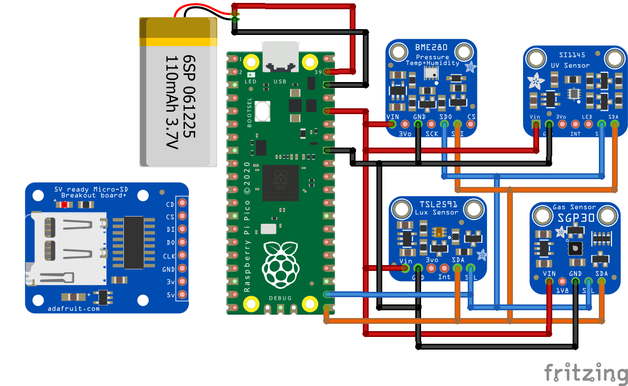
This is just a WIP Wiring between sensors and Pico
What is tested and working
- Turning on the pi-top[4] from the Raspberry pi Pico - Thanks to @duwudi for mentioning this is even possible and thanks to @wil for providing the UI PCB and information on wiring
The reset switch is for testing purposes only and using the UI PCB to access the Power switch Pin on the PMA
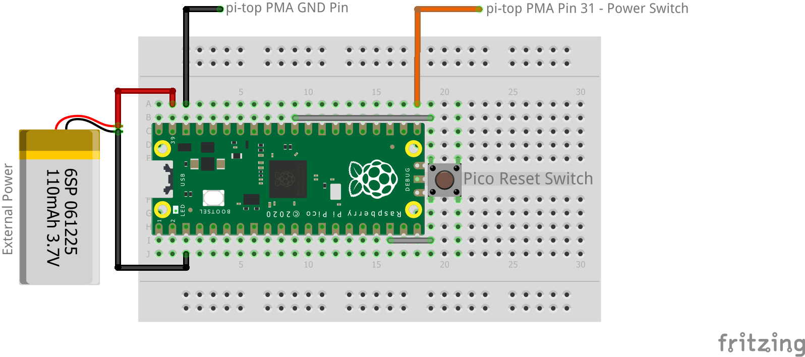
Python Code - Turn on pi-top[4]
from machine import Pin
import utime

wake_sw = Pin(16, Pin.OUT, Pin.PULL_UP) #this can be any GP pin GP22 recommended
led = Pin(25, Pin.OUT) # pin for onboard Pico pin
wake_sw.value(0) # sets to logic low

wake_sw.toggle() # toggle logic low to high
led.toggle() # turn on Pico LED
utime.sleep(1) # wait 1 second
wake_sw.toggle() # toggle logic high to low
led.toggle() # turns the onboard LED off
Design
This is a current work in progress - I have made a Symbol and footprint for the 4 Adafruit Sensors
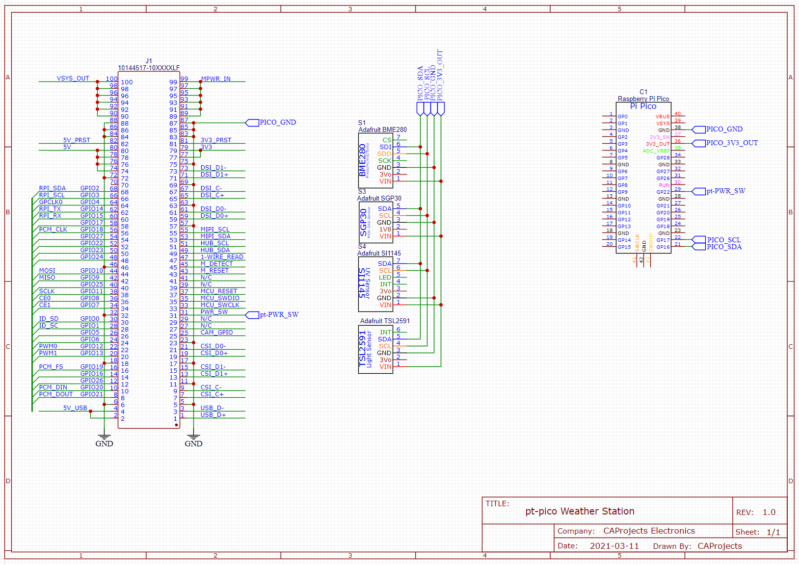


 , you may wonder how?