GPS Project help

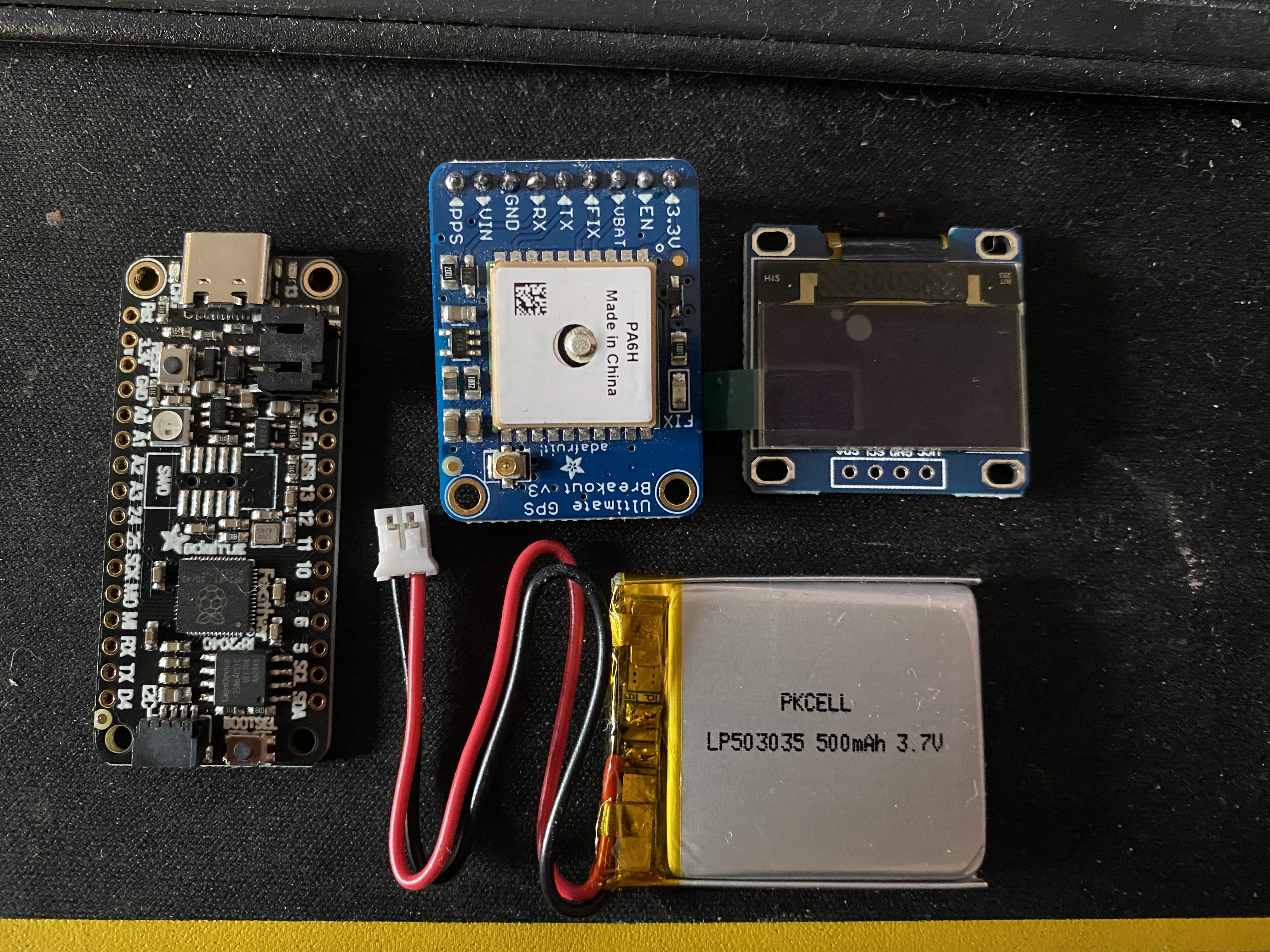
So I got myself an Adafruit Feather RP2040 and was thinking of not using it till they update CircuitPython to include a couple needed features like multi threading and PIO and deep sleep functions. This was going to be my dedicated CircuitPython board so I am going to do my best with MicroPython or C/C++ or even Arduino

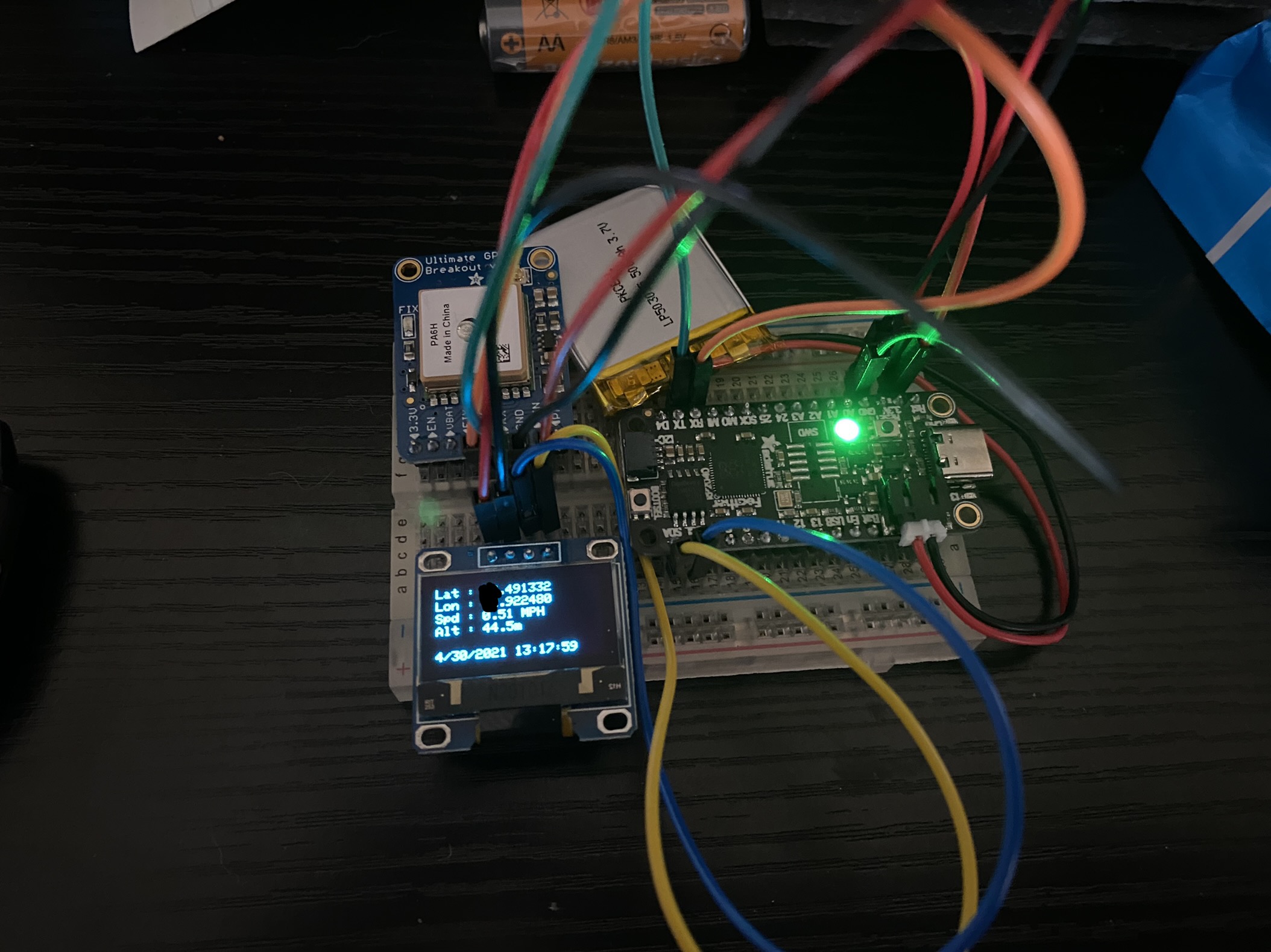
I think you may be able to tell what this project is going to be :stuck_out_tongue:

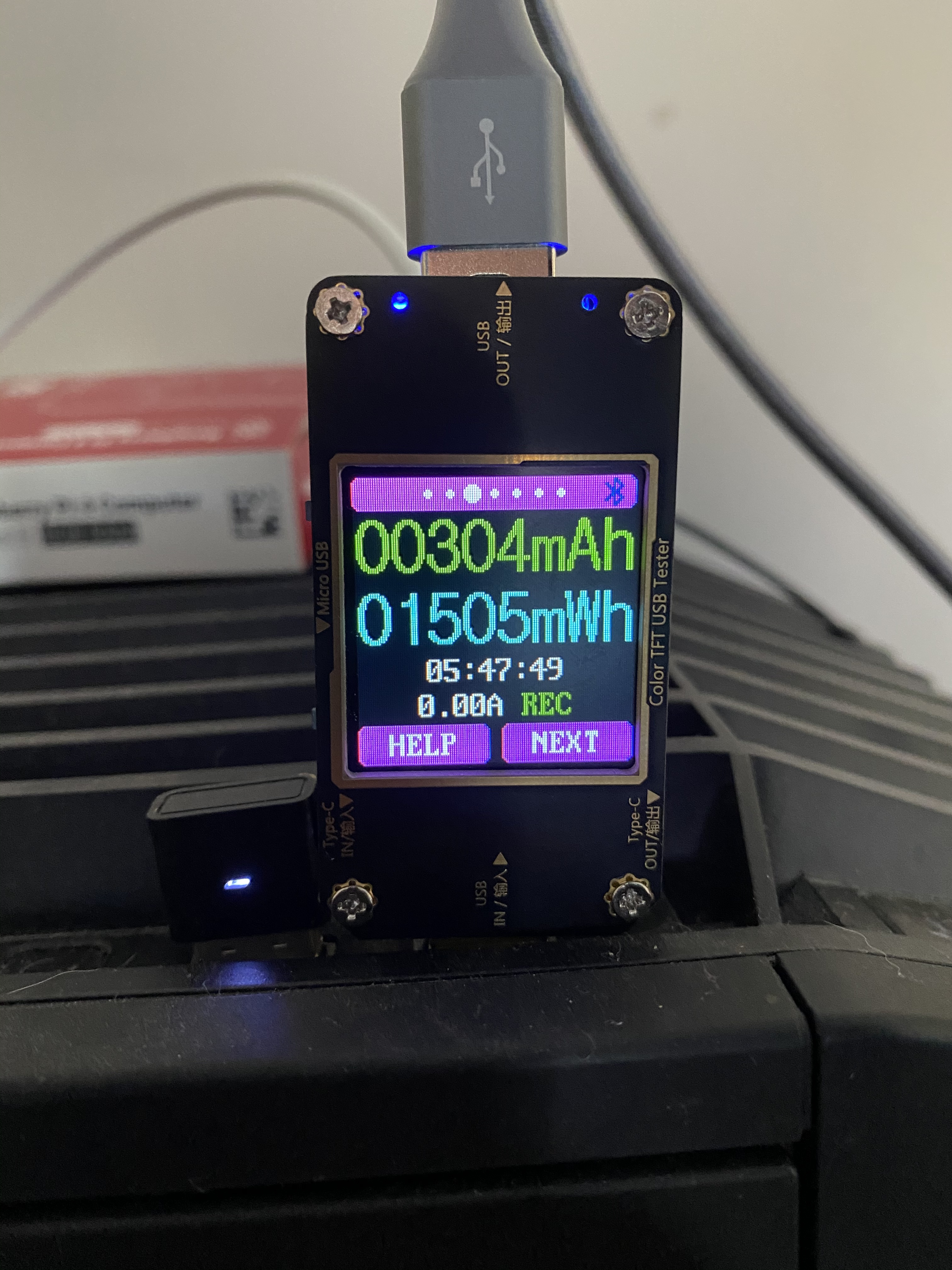
one nice thing about the Feather 2040 is that it has a built in charger, charges the battery when the USB is plugged in.

Now down side is that they decided not to have a built in battery monitor as they did not want to use up 1 of the 4 DAC but I wish they did add that and only have 3 DAC. This making the builder to figure all that out themselves

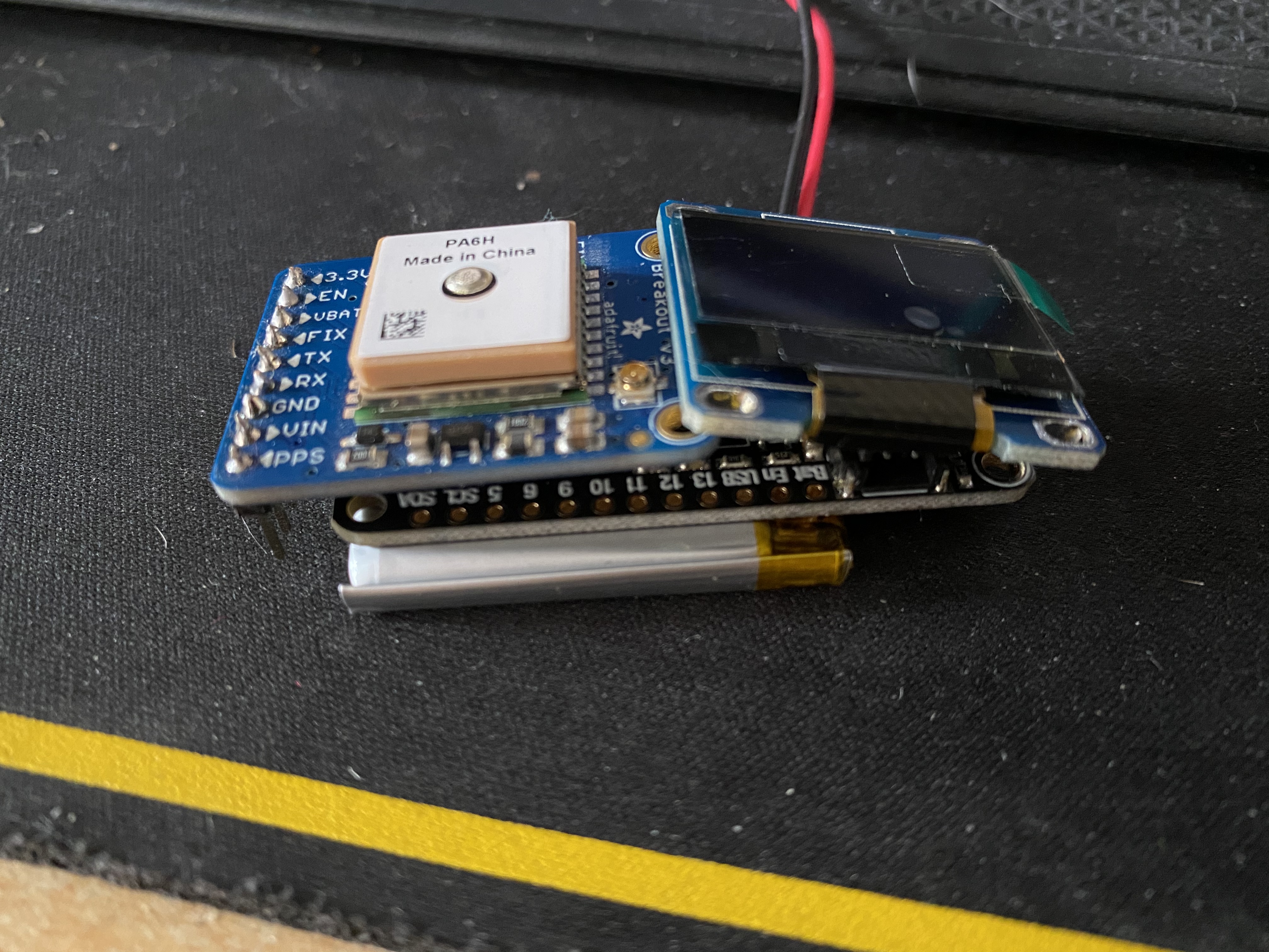
I know the code to get this project done but also need to look at a case to house it all, thinking of maybe stacking line this

I also have a high gain gps antenna that connects to an SMA to uFL cable that the case would need to accomodate. And would like some sort of switch to turn the power on and off

So couple questions,

  • Any suggestions on a switch to use?
  • Should I make an interphase board to mount all the components to?
  • Should I maybe go eInk for the display instead of OLED?

This is most likely be a permanent build with adding only software improvements over time like using the NeoPixel LED on the board for certain statuses and improve optimisations. I have no real interest in this board so don’t mind a single use build for it

@CAProjects I’m not surprised it doesn’t have a battery monitor in it, that stuff can get really complex - most simpler devices like this would just use a voltage-based cut off at around 3.2V (you can go to 3V but I’d recommend 3.2V just to be sure). It would be challenging to get a battery percentage from just voltage information alone.

For a power switch, a simple latching on-off one will do - that is unless you want some code to trigger before the power is cut off. In that case, things get a bit more complicated from a power management perspective as you’ll need a MOSFET switch arrangement (usually called a load switch) to cut power, and your MCU would need to go into a deep sleep mode whilst still listening for further switch presses. So yeah, I’d just go with a latching type on-off one.

In terms of e-ink vs OLED - that depends on your requirements. If you’ll mainly have static images on the display then e-ink makes sense as your power draw would be reduced a lot.

What do you mean by interphase board?

Interface board to attract the feather rp2040 and the rest of the devices to give it a cleaner look and use standoffs for the oled/eInk board for more stability/preventative measure to prevent breakages etc. So basically something to go between the gps and screen and the feather board otherwise I would have to look to get a gaze with slots in it to house them all together nicely.

Tbh I am not looking to re-use the feather rp2040 as, with more playing about with it there is more restrictions you can do with it especially with micro/circuit Python, for example, with what ever flavour of Python you choose, you cannot use the neopixel, it’s a status LED depending on what file is or is not uploaded to the feather. C/C++ gives better control of the board sadly.

As for the power I don’t need a shutdown action, just basically on and off. I am going to be getting the GPS once every 30secs and record the information, that’s all it’s going to do. The need for it is mainly for when I can get out and about with the husky in areas that mobile signal is not existent. Battery capacity will require testing tho, looking to get it running for at least 20-30 hours, which I think is achievable.

Ok then maybe a 3D printed enclosure would be your best option? Would tidy it up quite nicely and reduces the need for any PCBs which take more time to get made.

I think 20-30 hours should be doable, worth a test to see though!

Interesting test I done with the gps powered at 1 sec interval and a blinking LED on and off every second without an active antenna using arduino core I got this result

image

This would give about 23 hours for a 1200 mAh lipo I think

with an active antenna its sitting at low: 0.055A and High: 0.06A

And everything running on Arduino Core on battery power
image

Do you know the power draw by each component in the system?

not of the top of my head, did have it on a drive with other projects but that drive failed and is on its way to get data recovery on it, i back up that drive once a month but forgot that past couple months due to being busy so that data was not backed up :frowning:

I know i can extend the battery life if using deep sleep function but still need to look into that