
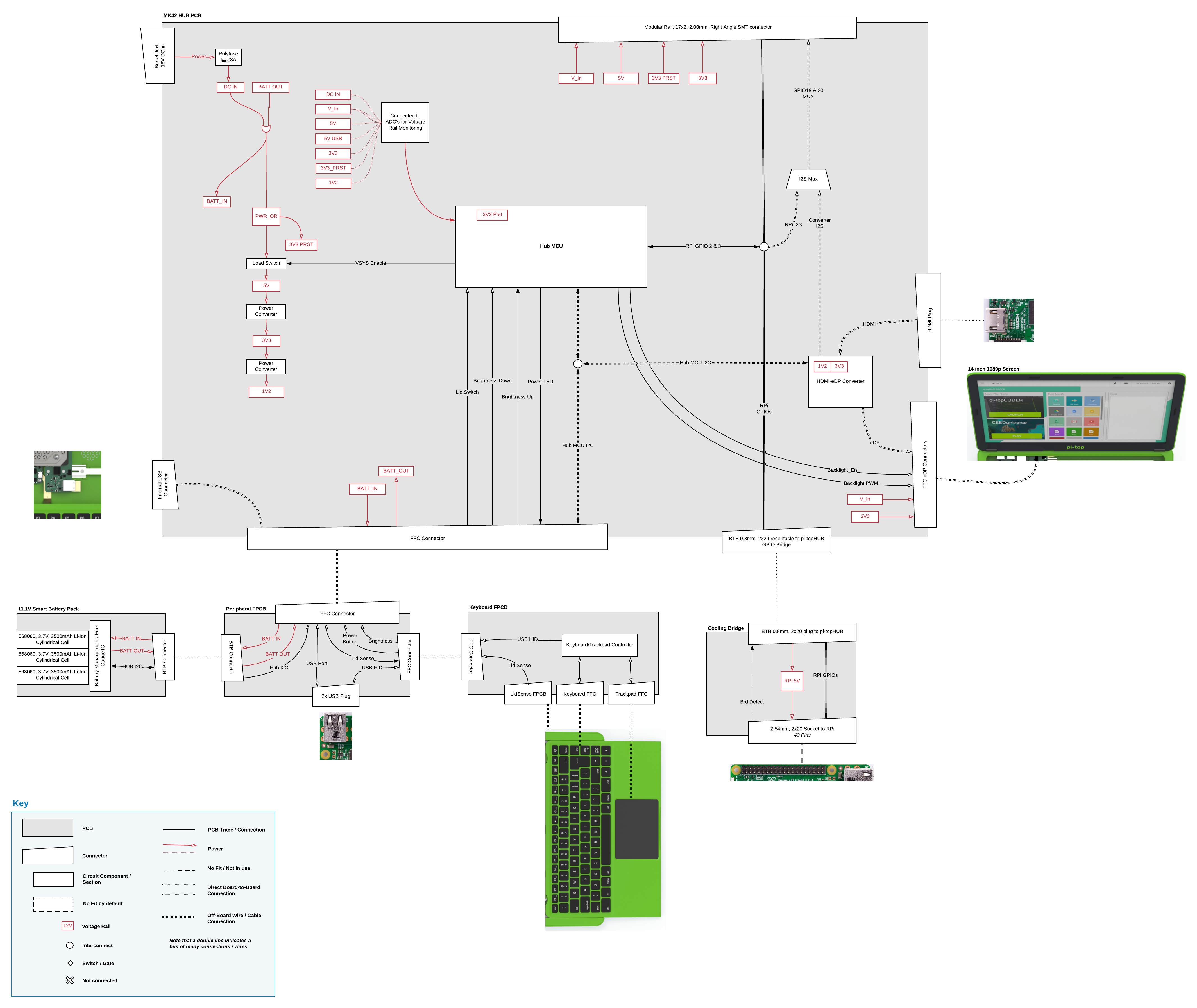
Here’s the block diagram for the pi-top[3]. We recommend that you download the image so that you can see the full detail
1 Like
thx, could be nice to have the pitop hub2 pcb diagram . will be nice to modded and adapt to raspi4.
@AkiAfroo Did you mean the schematic diagram or the PCB Layout? If you have any specific questions about interfacing with the hardware then I can help you out with that!
yes, both. there are couple of pcb companies that can adapt the hub2 to the new pi4. I spent 300 euros on pitop3 a year ago so I couldn’t use it with the pi4. and to be honest with the raspi3 the system is very slow. I know that the pitop3 case needs a little modification since the pi4 ports have changed but it is something that I am willing to assume.
I know it is not your fault (pi4 new layout) but it would be interesting if you will provide us with a solution to that problem. Maybe it could be a line of business for you and if it is not, it would be good if you could share the schematic diagram as long as there is no problem with copyright.
@AkiAfroo I completely understand what you mean. We’re also quite frustrated that we can’t use this more powerful Raspberry Pi inside the pi-top[3] for the moment, though we are working on it. Unfortunately we can’t release the hub schematic or layout because they are our IP and if we were to release it to the community it would be likely that copy-cat companies would then try and design their own versions.
The other issue is that the hub is only part of the problem, there’s also the ethernet port blocking the USBs. That means a redesign of the plastic so that it could accept both types of Pis, and a redesign of the FPCB that has the USB Plug.
Sorry we can’t offer a better interim solution right now but as promised, we’re working to get a solution!
I perfectly understand , And as I said I would not mind paying for an adapter or solution that makes me use the pi3 again
Thank you for the quick response
pd, for future updates do not forget to add some kind of fan like
https://learn.pimoroni.com/tutorial/sandyj/getting-started-with-fan-shim
cheers!
@AkiAfroo Have a look at my first attempt in putting a RPi4 inside a pi-top[3]. Please feel free to post any comments there on what you would like to see in improving it!
nice! i will take a look right now. i was thinking something similar some months ago. lets check it ., thx !
Hi,
I am trying to use FPC FFC cable to connect the pitop hub to the GPIO of a pi 4 (replacing the cooling bridge). Please can you post some more details of the board to board connector from the cooling bridge to the pitop hub, enough details of the plug and receptacle for me to buy ZIF connector plug to attach to the pitop hub receptacle?
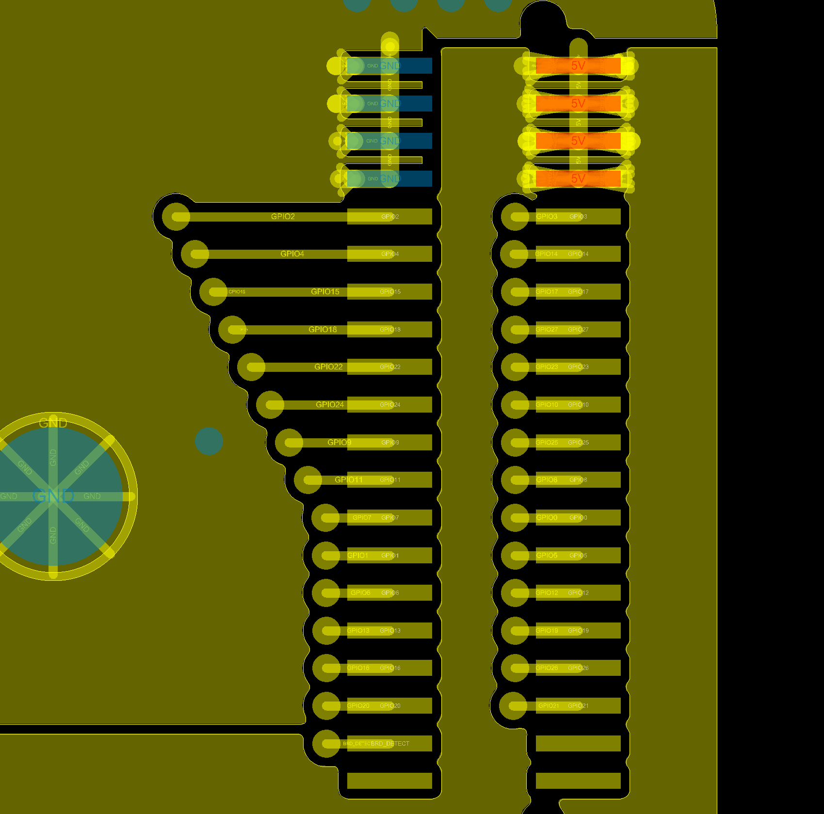
This is the BTB connector of the cooling bridge. Be careful with your pinmapping as this is the bottom layer of the board as seen from the top. i.e. the GND pins connect to the top left of the BTB connector of the hub. I hope this helps! Please feel free to show what you come up with
Hello
I am also adding a raspi clone to the PiTop [3].
Just want to make sure which signals are necessary from the HUB to the Raspi.
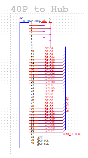
I see at least it needs the 5V and GND connections. Its also necessary to connect
BRD_DETECT and GPIO 1 & 2?
Also , which type of BTB SMD connector is that?, in case I want to build a custom bridge connection
Hi @perello, you’ll need BRD_DETECT connected to GND, 5V to supply power, GPIO2 and 3 for I2C communication between your SBC and the pi-top Hub, though if you’re using an OS that isn’t pi-top OS then you won’t need I2C.
It’s made by one of our suppliers in China, unfortunately I dont’ have a datasheet for it at the moment though I’ll try and get one for you.
Manufacturer:Goxconn
P/N: 3108-40-240M
Description: 0.8mm BTB, 20x2pin, 4mm mated height
Thanks! thats all I need. I am using armbian mostly.
What is pit-top OS doing with hub I2c?
I do try to source a compatible connector to do a simple power harness.
The pi-topHub (the slave) communicates with the Raspberry Pi (the master) over I2C. The RPi collects battery information, fetches the status of the keyboard/trackpad, and the lid sensor (turns off the screen when the lid is closed). It’s also how the pi-top tells the RPi to trigger a soft shutdown when the power button is held for 3 seconds or when a shutdown is triggered from within the os.
If you were to use another OS or SBC and were to shutdown the OS, the RPi would soft shutdown though you would see the green light of the hub, the red light of the RPi and the backlight of the screen still on. You would then have to press and hold the power button on the keyboard for 5 seconds to trigger a hard shutdown of the hub and therefore cut off power to the RPi.
Thanks for posting the block diagram. It’s helpful! A couple questions…
-
I assume “V_in” comes from somewhere around the PWR_OR block, correct? …and thus its voltage would fluctuate between the DC_in and BATT_OUT and the battery voltage (~11 V - 18 V)?
-
From the diagram, it looks like both V_in and 5V are available on the rail outside the hub PCB, correct? Practically speaking, how many watts are available from each of those?
Context: I’m trying to sketch out a power budget for what additional components I can stick in the pi-top and still end up with reasonable battery life. I know the USB port on the hub will supply 2.5 W, but I’m hoping to pull more than that form somewhere else. Unfortunately my pi -top is still in transit, but that shouldn’t hold up the design phase of my project! 
Hi @Pineapple
- You’re right, V_In flucturates between the battery voltage and the DC_In voltage.
- That’s also correct, you can find which pins they’re available on here. Both pins are limited to 0.5A.
1 Like
Hello,
I try to connect my own FPGA based board to pi-top[3]. I tested basic connection to the HUB and now I want to control the HUB using I2C as you describe in one of the previous post (getting battery information, fetches the status of the keyboard/trackpad, soft shutdown, …).
Can you please provide a detailed description of the registers which are accessible using I2C ?
Address of each register with meaning of its value. Which registers are writeable and which are read-only, etc.
That would help me a lot
Thank you
1 Like
Hello. Im new on this site. Already read all conversation regarding the block and help me a lot. Because i already buy one used the same come with a pi 3+ but its broken. Also didn’t come with the bridge. After all my plan if to reuse with an smartphone. Already made small solder for the pin 37 for the BTB connection to gnd and hopefully with the hub i have a success.
Now with this i have 3 question.
How can i get the battery to work because only work when i plug in the dc / ac adapter. Already buy one universal for 18 v but its 3.5 A. (because not come with charger)
It’s possible to found any pin to provide more energy to the hub and charge the smartphone because the usb on the pi-top hub not give to much power.
What its the pin for install an external speaker.
Please need your support.
Thank You