
my God! everytime i want to mod my pi3… appears new ideas. xD
I know how you feel, I’ve been trying to plan a v2 of my first mod, but lots of great ideas coming out of here so i’m not sure where to start!
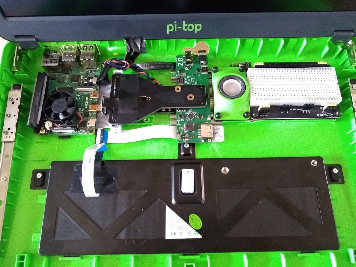
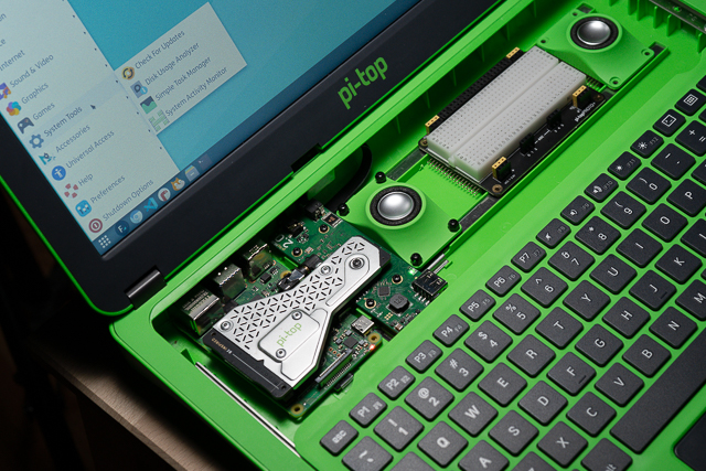
My FrakenTop v2 Pi4!
Was made by pulling out the old USB connector, Mounting the Pi4 and connecting the gpio cable, cutting and then soldering to length onto a right angle header expansion.
Then once I had the position for the Hub cutting the old mounting rails to length to reuse the old mounts and cutting away the plastic that was in the road of both ribbon cable and mounting connectors so no rubbing would occur.
Made some minor modifications to the micro-hdmi cable so it was as slim as possible. There is an aluminium heat sink on top of the Pi to try and keep it cool, might need to add a fan later on.
Best thing is that both the proto+ fits in as well as the keyboard closes without issue. The keyboard and mouse pad are both functional as well as the USB on the Hub board.
Took me about 5-6 hours to modify. Only regrets is over cutting the USB connector holes and the holes for the power and headphones to outside of the case aren’t the best aligned so they are larger than needed.
5 Likes
I like the use of the right-angle GPIO connector - it might solve the issue I had of the connector and cable (from the Pi GPIO) preventing the keyboard from sliding back.
The parts I used were:
HDMI to connect Pi to Hub
-
DIY USB or HDMI Cable Parts - 10 cm Ribbon Cable: https://thepihut.com/products/diy-usb-or-hdmi-cable-parts-10-cm-ribbon-cable
-
DIY HDMI Cable Parts - Right-Angle Micro-HDMI Plug: https://thepihut.com/products/diy-hdmi-cable-parts-right-angle-r-bend-micro-hdmi-plug
-
DIY HDMI Cable Parts - Straight HDMI Socket Adapter: https://thepihut.com/products/diy-hdmi-cable-parts-straight-hdmi-socket-adapter
Stereo Cable
I used wire to extend the 3.5mm jack. I drilled through the rivet and removed the connector from the Hub PCB and extended the wires by soldering. With hindsight, a less destructive method like this might be a better option (but this has not been tested so I can’t guarantee this will fit in the space):
-
Right-Angle 3.5mm Stereo Plug to Pigtail Cable: https://thepihut.com/products/right-angle-3-5mm-stereo-plug-to-pigtail-cable
-
Breadboard-Friendly 3.5mm Stereo Headphone Jack: https://thepihut.com/products/breadboard-friendly-3-5mm-stereo-headphone-jack
Gerneric Parts
I used a 3.6 mm ply as the base, with 6mm threaded inserts pushed in flush to the bottom face (and glued). This results in the inserts protruding 2.4 mm from the top face of the base. This is enough space to run the ribbon cable under the Pi, but ideally a little higher would help with cooling on the underside of the pi.
-
2.5 mm inserts for the raspberry pi screws: https://www.amazon.co.uk/dp/B07R6HST85/ref=pe_3187911_185740111_TE_item?pldnSite=1
-
2 mm inserts for the battery, rails and monitor screws: https://www.amazon.co.uk/dp/B07R6HT9FZ/ref=pe_3187911_185740111_TE_item?pldnSite=1
You can reuse the existing screws to fix everything. However
-
I used slightly longer M2.3 self tapping screws to fit the bodyboard slides to the wood: https://www.amazon.co.uk/Phillips-Laptop-Computer-Self-Tapping-Electronic/dp/B07GP3CM8M/
-
I also bought a these as I damaged the head of an M2 screws taking it apart: https://www.amazon.co.uk/Phillips-Countersunk-Electronic-Accessories-Samsung/dp/B07HC8CJ68/
HTH
2 Likes
I wanna upgrade to RockChip64
Is it possible?
I’m sure it’s possible, it’s just a question of how difficult it would be 
At first glance, it looks like the power may be tricky because the Rockchip wants it through a barrel connector. Not sure if it will take power through the IO pin header. It also looks like it consumes quite a bit more power than a Raspberry PI, so battery life and heat dissipation would be two additional things to look at.
I’ve heard members of the community using the ODroid and I myself have used a Tinker board in the pi-top, though it does really depend on the single board itself. Do give it a try and let us know how it works out
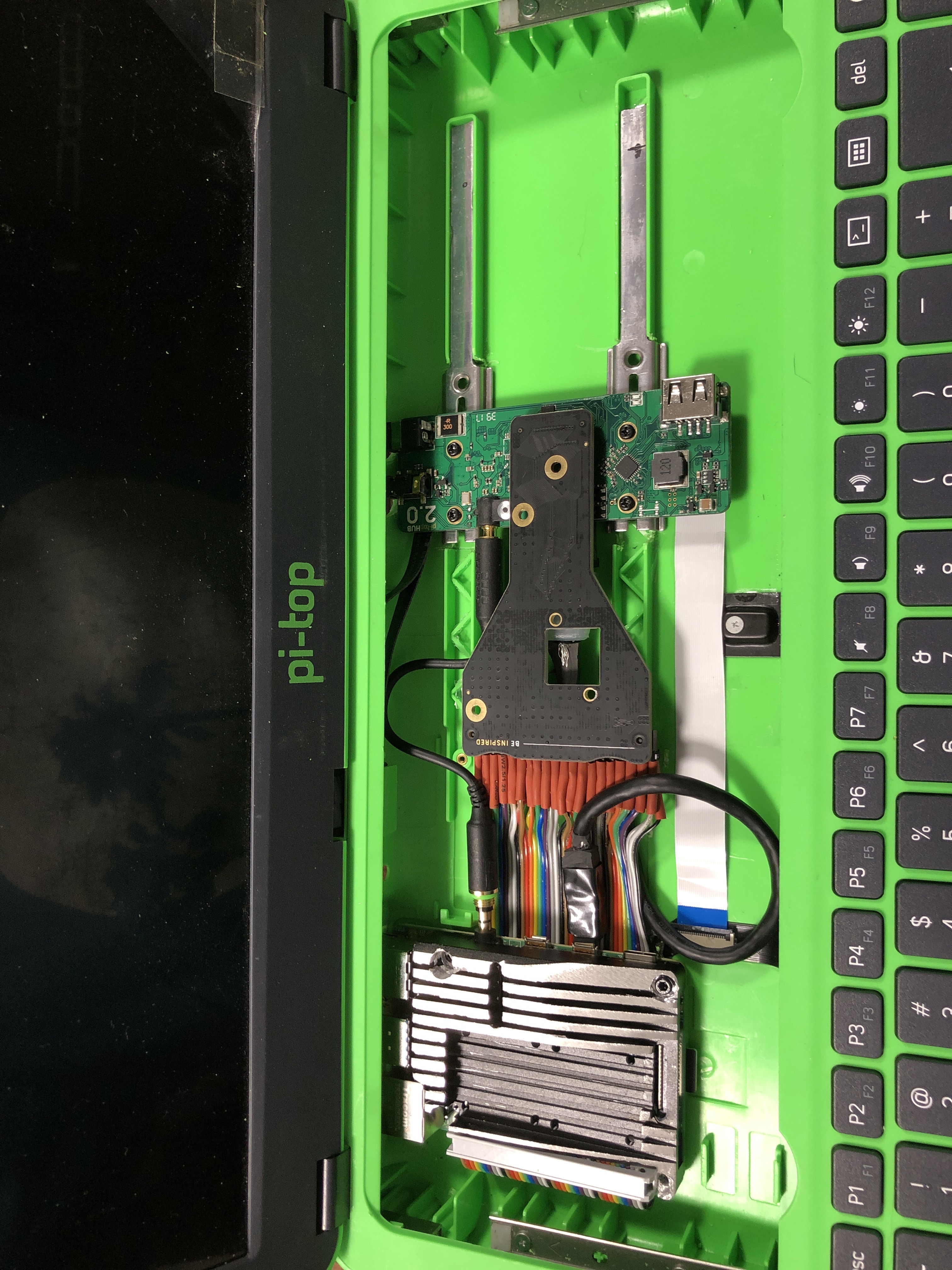
From a hardware point of view the NanoPi M4V2 looks like a nice drop-in replacement:
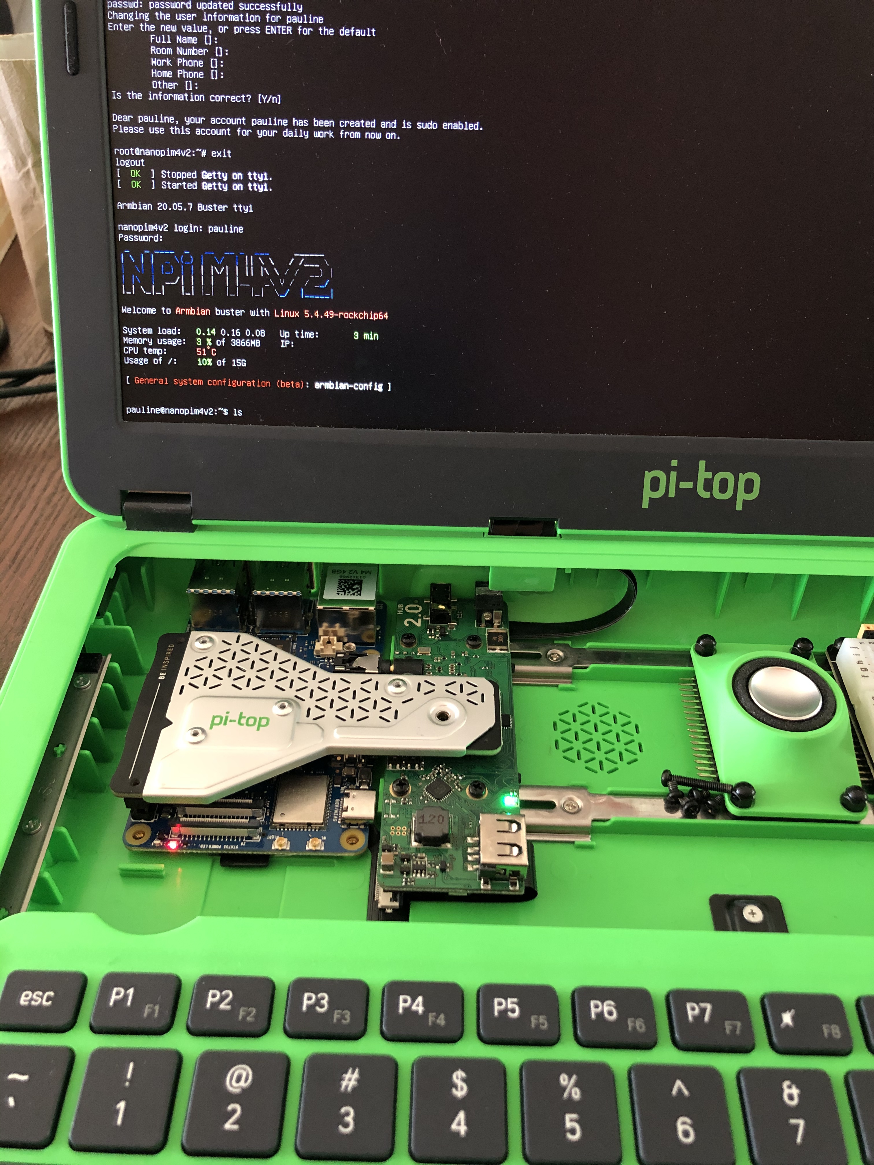
Performance is superb, however sound, battery indicator, i2c, poweroff, GPU acceleration are not working yet with armbian. I would love to keep pi-top os but it’s probably beyond my ability to merge it with armbian boot and kernel.
3 Likes
That still looks awesome! I think you may still be able to use the pi-topSpeaker as it can also take HDMI audio from the single board computer and turn it into I2S Audio via the hub.
RE the battery: RPi OS had a package you could install in order to get the battery indicator working on just regular though I can’t seem to find it anymore.
There’s this forum post discussing it
https://www.raspberrypi.org/forums/viewtopic.php?t=204021
Do let us know if you can get it working though!
-RezIN
Thanks for the interest and the pointer for the battery indicator!
I’m opening a separate thread to gather info on this matter.
After a little more playing around, I managed to add the Fan Shim and fit in all back in the original case:
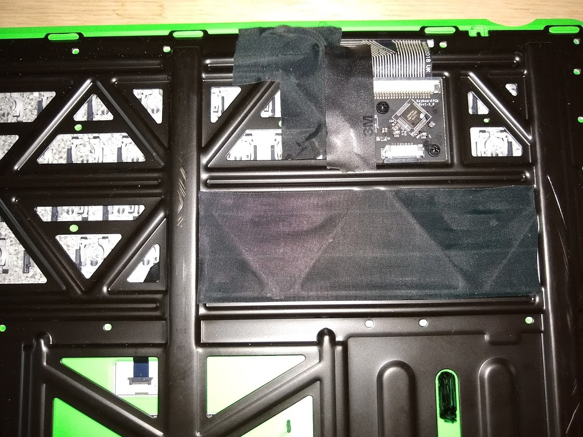
The fan works brilliantly, you can set the temperature limits at which it turns on and off. I had to file down the GPIO connector so the keyboard would slide closed:
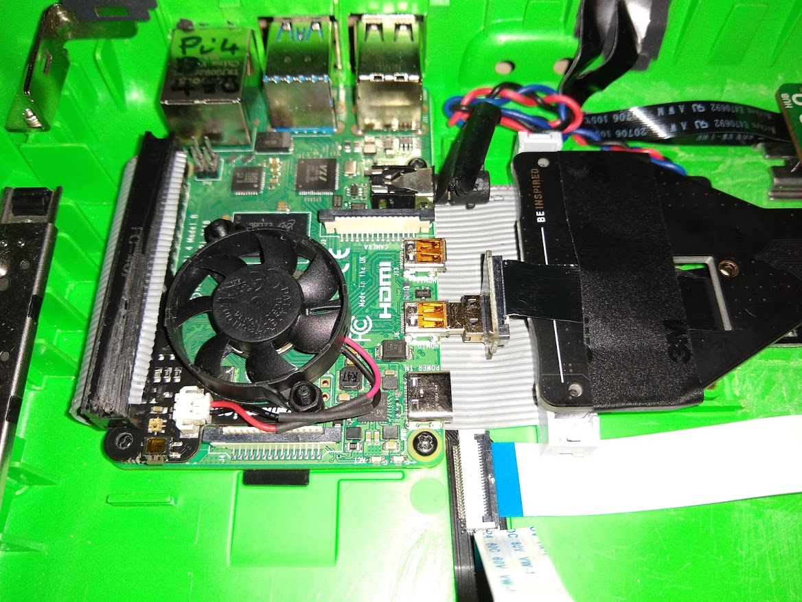
I also had to tape the HDMI to over the original GPIO / Cooling PCB (see image above) and put tape over the connector on the underside of the keyboard assembly as the connector kept catching on the HDMI cable when sliding the keyboard open.
3 Likes
Wondering what has been done with the led that’s been cut out as well as the ribbon cable attached.
Inspiring! My case is prepped and parts ordered. I’ve wanted to do this for some time! Thank you all for sharing your work!
Hello,
LED is still in the same place.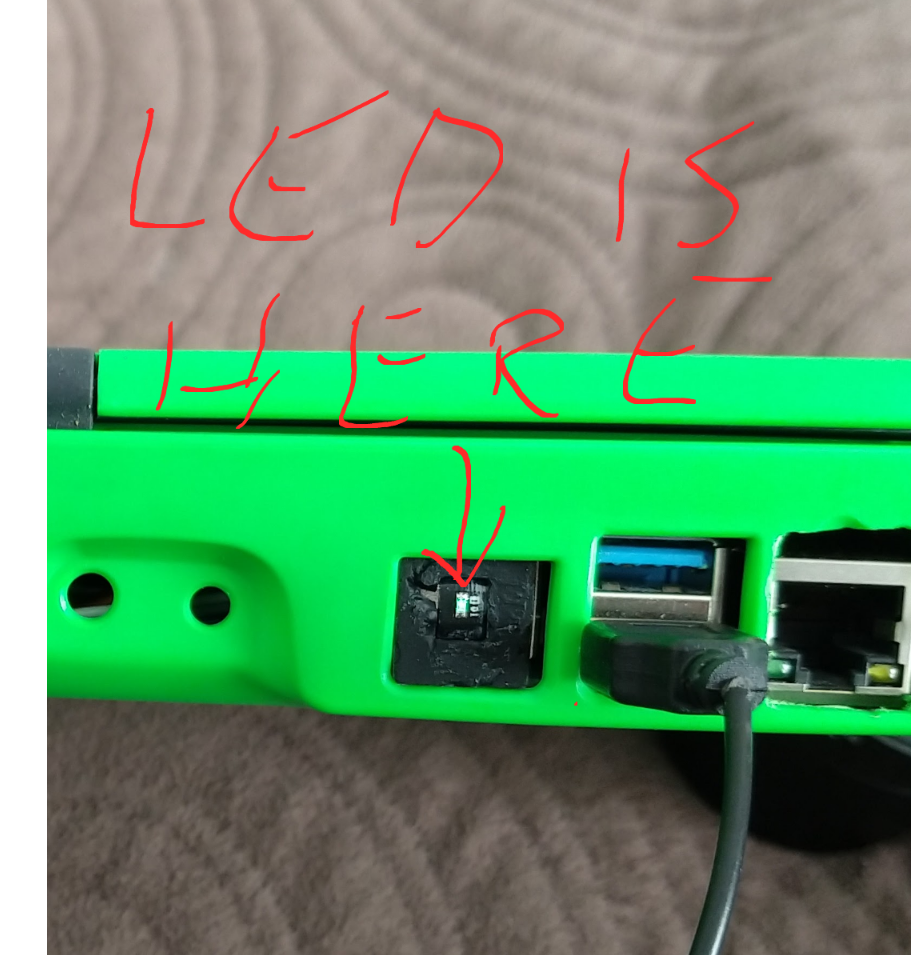
1 Like
@Steve @HazardChem How did you guys take the metal plate off of the power bridge? The screws don’t seem to be regular screws. Thanks for any help!
Hi Sujaygarlanka,
They are pop rivets, not screws. To remove you need to carefully drill them out, don’t use a big drill otherwise you will drill the PCB. Find one that will drill the centre part out and not touch the edges.
Thank you! Drilling it out worked very well.
Hi all, my first posting here: Pi-Top [3] modded with RPi 4 and current Sirius OS!
Hardest part of the mod is hidden beneath the cooling bridge: I removed the stock HDMI connector and replaced with micro HDMI. Cutting apart a HDMI > Micro HDMI adapter got me the connector, the correct pinout, and revealed that there are 5 shielded, twisted pairs of data connections to deal with, plus a number of unpaired wires - 16 wires in all. Soldered, de-fluxed and wrapped these in Kapton tape.
Fit isn’t perfect as micro HDMI connector is squeezed beneath Hub PCB, and Pi 4 ports seem to have shifted a little bit more than just the ethernet and USB 2.0 trading places, but using a drill, hobby knife, small files and some patience, I thought the revised rear panel cutouts came out pretty good.
Initial attempts to run Sirius OS got me a black screen, but I found that if I connected RPi directly to TV via HDMI and completed initial setup there, it then worked fine on Pi-Top.
1 Like
Awesome work, Jeff - THAT is an elegant solution!
I pondered on the blog post whether such an approach was possible but wasn’t sure so really glad to see you’ve achieved it!
Would you be able to provide more photos showing the micro HDMI connector on the hub v2?
Also, did you gently ease up the peripheral FPCB USB to connect it to the RPi4’s USB2 ports or would that have been too much of a stretch and you had to plug them in the USB3 ports instead? Would be neat to see photos of the rear panel cutouts too
For the less advanced solderers amongst us, would you mind awfully going into a bit more detail about how you desoldered the existing HDMI port from the hub v2, detached the micro HDMI from the adapter and soldered it to the hub v2? If you have another such adapter and would be willing to take it apart in the same way to show step-by-step photos of this process that would be really great!
Congratulations on such a neat piece of work!