The pi-top [3] + Raspberry Pi 4 (Franken [3])

That still looks awesome! I think you may still be able to use the pi-topSpeaker as it can also take HDMI audio from the single board computer and turn it into I2S Audio via the hub.

RE the battery: RPi OS had a package you could install in order to get the battery indicator working on just regular though I can’t seem to find it anymore.
There’s this forum post discussing it
https://www.raspberrypi.org/forums/viewtopic.php?t=204021

Do let us know if you can get it working though!
-RezIN

Thanks for the interest and the pointer for the battery indicator!
I’m opening a separate thread to gather info on this matter.

After a little more playing around, I managed to add the Fan Shim and fit in all back in the original case:
image

The fan works brilliantly, you can set the temperature limits at which it turns on and off. I had to file down the GPIO connector so the keyboard would slide closed:
image

I also had to tape the HDMI to over the original GPIO / Cooling PCB (see image above) and put tape over the connector on the underside of the keyboard assembly as the connector kept catching on the HDMI cable when sliding the keyboard open.
image

3 Likes

Wondering what has been done with the led that’s been cut out as well as the ribbon cable attached.

Inspiring! My case is prepped and parts ordered. I’ve wanted to do this for some time! Thank you all for sharing your work!

Hello,
LED is still in the same place.Screenshots_2020-09-01-19-06-50

1 Like

Good information thanks for sharing
vmware

@Steve @HazardChem How did you guys take the metal plate off of the power bridge? The screws don’t seem to be regular screws. Thanks for any help!

Hi Sujaygarlanka,

They are pop rivets, not screws. To remove you need to carefully drill them out, don’t use a big drill otherwise you will drill the PCB. Find one that will drill the centre part out and not touch the edges.

Thank you! Drilling it out worked very well.

_DSC0354
Hi all, my first posting here: Pi-Top [3] modded with RPi 4 and current Sirius OS!

Hardest part of the mod is hidden beneath the cooling bridge: I removed the stock HDMI connector and replaced with micro HDMI. Cutting apart a HDMI > Micro HDMI adapter got me the connector, the correct pinout, and revealed that there are 5 shielded, twisted pairs of data connections to deal with, plus a number of unpaired wires - 16 wires in all. Soldered, de-fluxed and wrapped these in Kapton tape.

Fit isn’t perfect as micro HDMI connector is squeezed beneath Hub PCB, and Pi 4 ports seem to have shifted a little bit more than just the ethernet and USB 2.0 trading places, but using a drill, hobby knife, small files and some patience, I thought the revised rear panel cutouts came out pretty good.

Initial attempts to run Sirius OS got me a black screen, but I found that if I connected RPi directly to TV via HDMI and completed initial setup there, it then worked fine on Pi-Top.

1 Like

Awesome work, Jeff - THAT is an elegant solution!
I pondered on the blog post whether such an approach was possible but wasn’t sure so really glad to see you’ve achieved it!
Would you be able to provide more photos showing the micro HDMI connector on the hub v2?
Also, did you gently ease up the peripheral FPCB USB to connect it to the RPi4’s USB2 ports or would that have been too much of a stretch and you had to plug them in the USB3 ports instead? Would be neat to see photos of the rear panel cutouts too :slight_smile:

For the less advanced solderers amongst us, would you mind awfully going into a bit more detail about how you desoldered the existing HDMI port from the hub v2, detached the micro HDMI from the adapter and soldered it to the hub v2? If you have another such adapter and would be willing to take it apart in the same way to show step-by-step photos of this process that would be really great!

Congratulations on such a neat piece of work!

Thank you for the kind words PhiPi!

I have keyboard and trackpad plugged into USB 2.0: The existing flexible PCB is more than long enough but I needed to take care not to simply crush it below the Pi.

I wish I had a step-by-step guide to converting Hub 2.0 to Micro HDMI which would allow anyone to replicate my work, but unfortunately, it’s kind of tricky and requires experience working with surface mounted electronics.

1 Like

More photos:
_DSC0421

1 Like

_DSC0355

1 Like

Not at all! :smile:

That’s good to hear! :sweat_smile: 
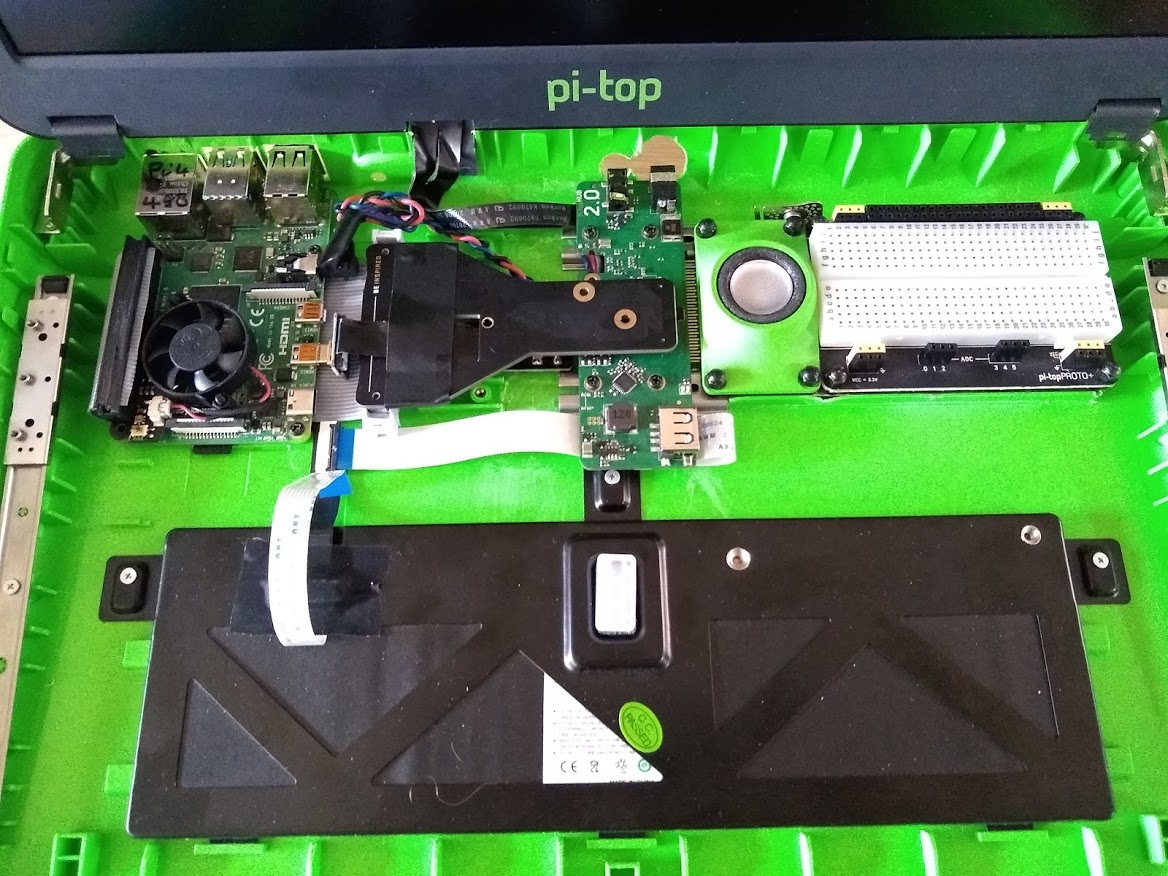
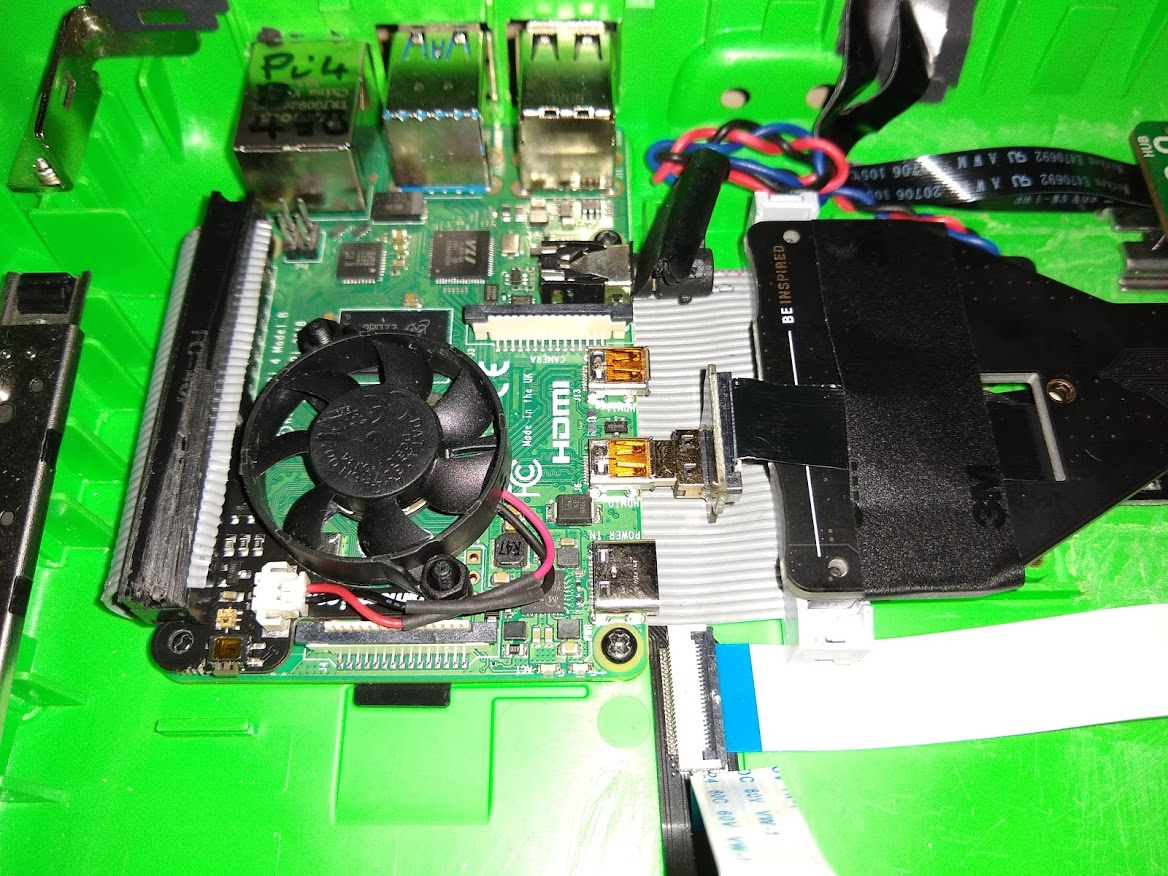
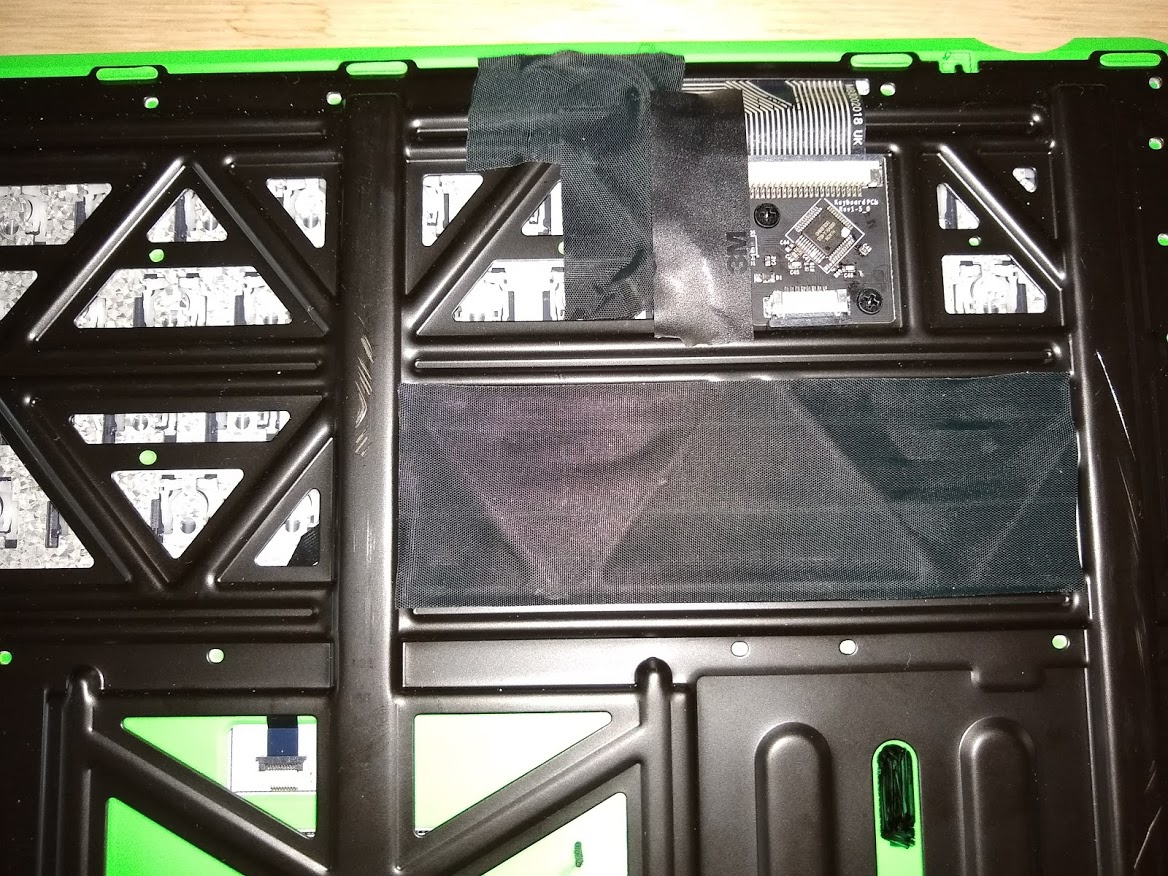
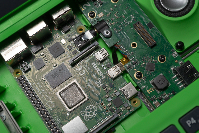
I got an iFixit set so should hopefully be able to carefully release the FPCB from the chassis in order to move the USB plugs into position for the RPi4’s USB2 ports. What did you use to release it?
I’ll see if I can integrate some sort of quick-release clip for holding the FPCB in place in the new position to avoid crushing it.

Ahh pity, I have some experience with trace tinning and through-hole soldering but none with SMT :worried: 
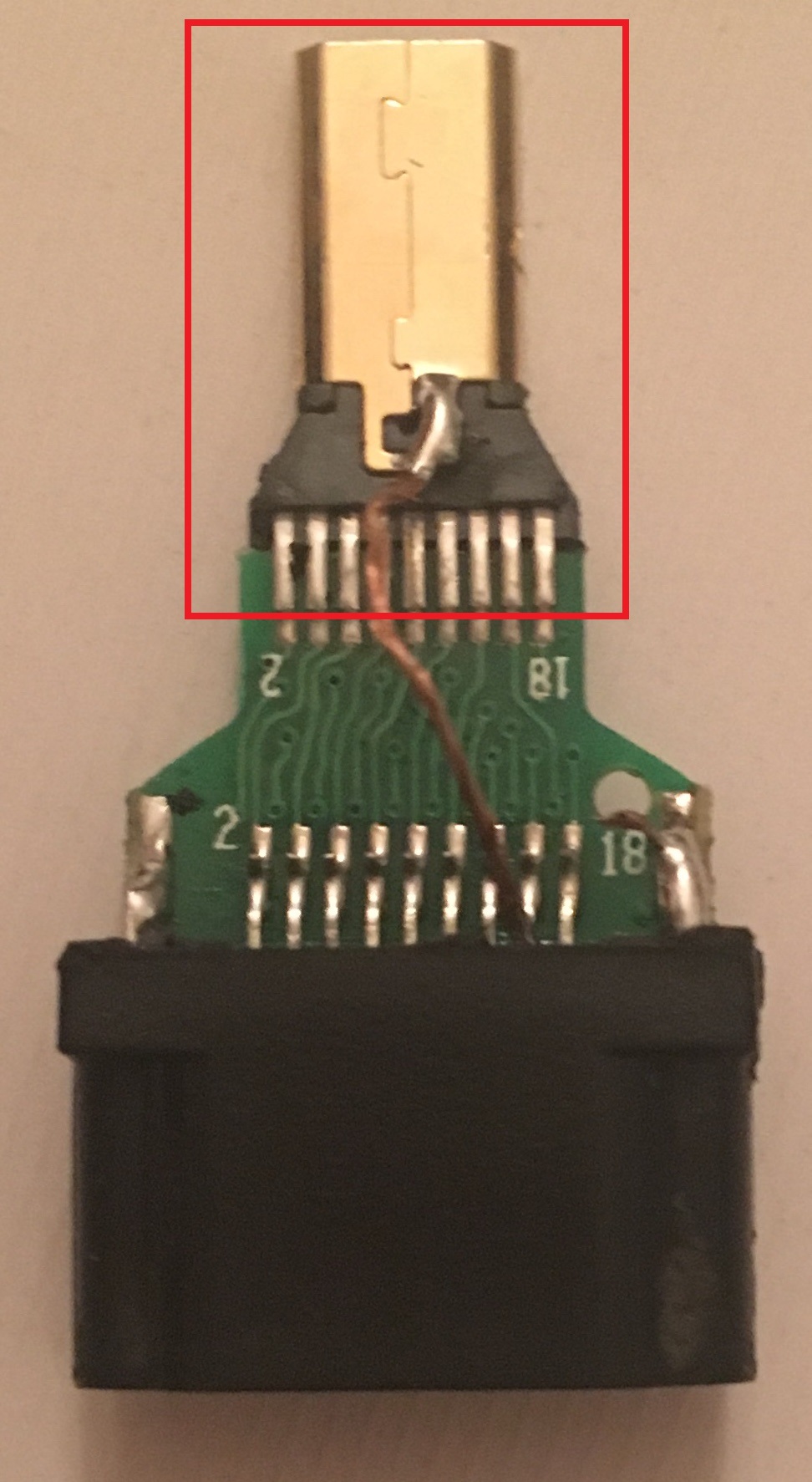
However, I’ve been reading up on (de)soldering SMT by hand and, with a bit of care, the techniques don’t sound too much more difficult… My plan is to have two Hubv2’s, one in the original RPi3B+ config and one in the RPi4 config so I can hotswap them interchangeably; that way I can still use RPi3-only OSes (like my old copy of pi-top Polaris) when I want.

Which brand microHDMI male —> HDMI female adapter did you use? With your experience, I wondered whether you might be able to give me some tips about what I should do based on the following photos; I ordered the Joy-it K-1482 from Conrad but when I used a craft knife to remove the plastic housing, the internals didn’t look like yours with multiple jumper wires:
image image image image

Any chance you might post a photo of the underside of your Hubv2?

I used only the micro HDMI plug itself, and have 16 or 20 (I forget) individual wires connecting it to the Hub V2 PCB. As you become experienced with reworking SMD by hand, I think you’ll find that the info that I’ve provided is sufficient.

You know how internet gurus make reworking SMD by hand look so easy? They don’t show you the many early attempts they completely bollixed a job beyond salvageability. Yup, the first few times you try this sort of thing, you should expect to totally fail, but if you stick with it, eventually you’ll start to fail less often. When those gurus say that it’s “easy”, they mean easy for the 0.1% of the population who went through the same learning process - I know I sure made a lot of messes.
microhdmi

2 Likes

@JeffS451 Woah! Just stumbled on this and I am insanely impressed :boom:

I have done this kind of meticulous HDMI wire soldering more times than I would like to admit, and I can safely say that it’s really not easy and requires a hell of a lot of patience and skill. We’ve actually had a few engineering team competitions on doing difficult soldering jobs like this and I think if you were taking part you’d be taking my crown :wink: :crown:

2 Likes

Thanks! I’ve just had a lot of practice, and it helps to have a microscope too.

1 Like