i’ve been thinking about this dilema, and it seems there are 2 issues
1 the physical port problems
2. the connector mismatch
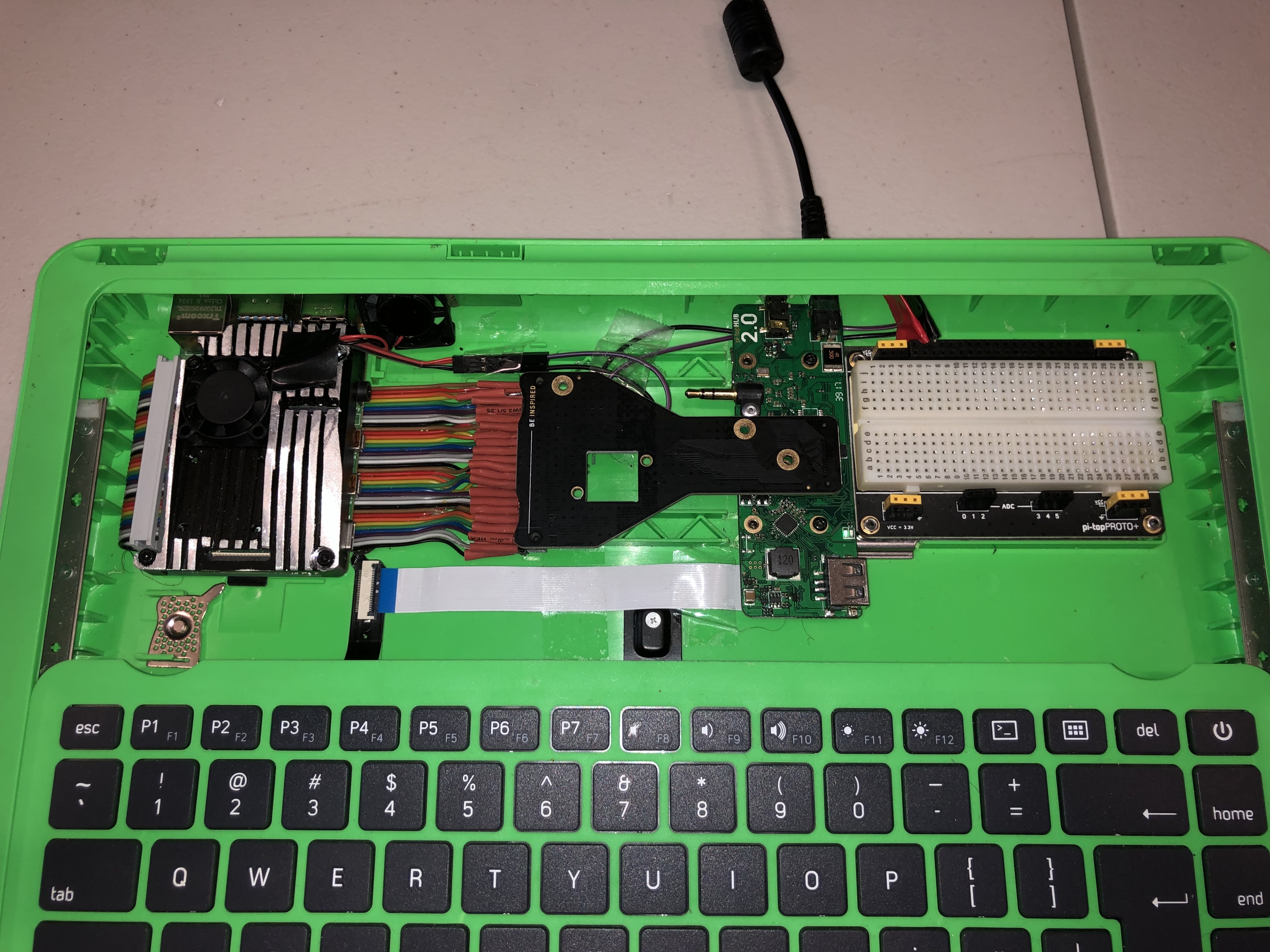
1 think the connector mismatch could be solved with a custom board. it would need to insert at 90 degrees to the other 2 boards (pi 4 and bridgeboard) so it would be edgewise
compared to the others.
it would have 2 micro hdmi male plugs on one side and full size hdmi female port to mate to the bridgeboard. 1 micro-hdmi would provide video to the lcd through the bridgeboard, the 2nd would supply a connection for an external monitor at the rear of the pi-top. so the card would have a micro hdmi or whatever is easiest to wire at the back of
probable rotated 90 degrees to match the orientation of the adapter board.
it could be a printed circuit board with any line buffering provided by smd components.
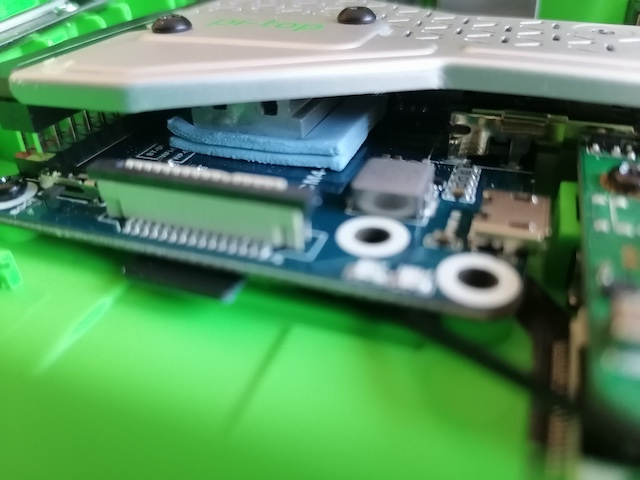
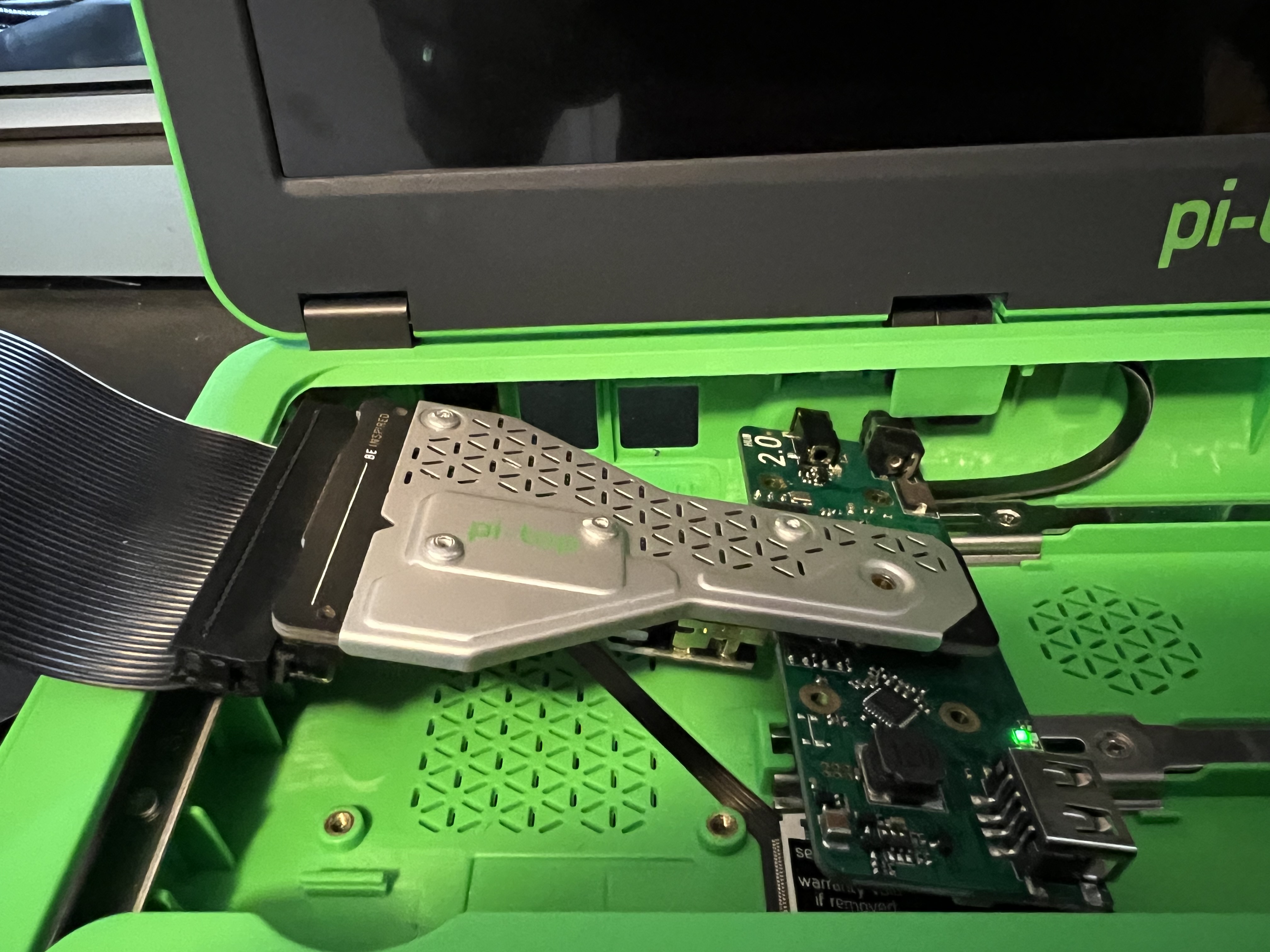
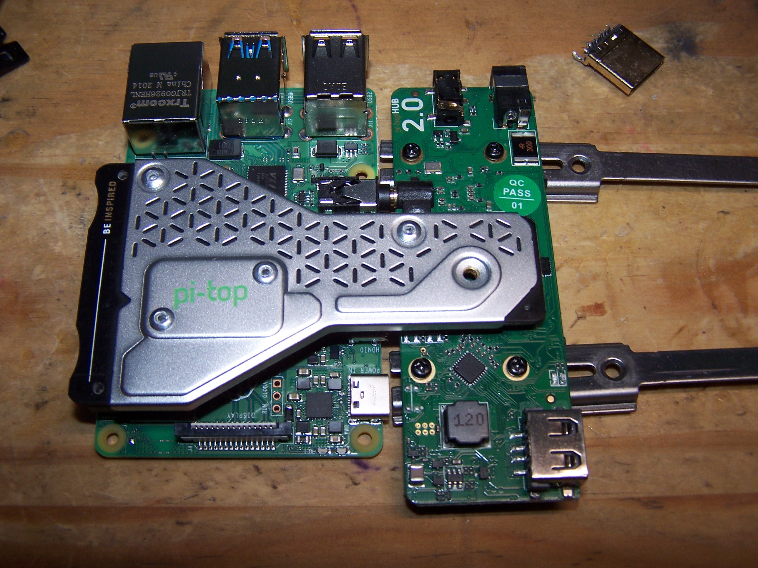
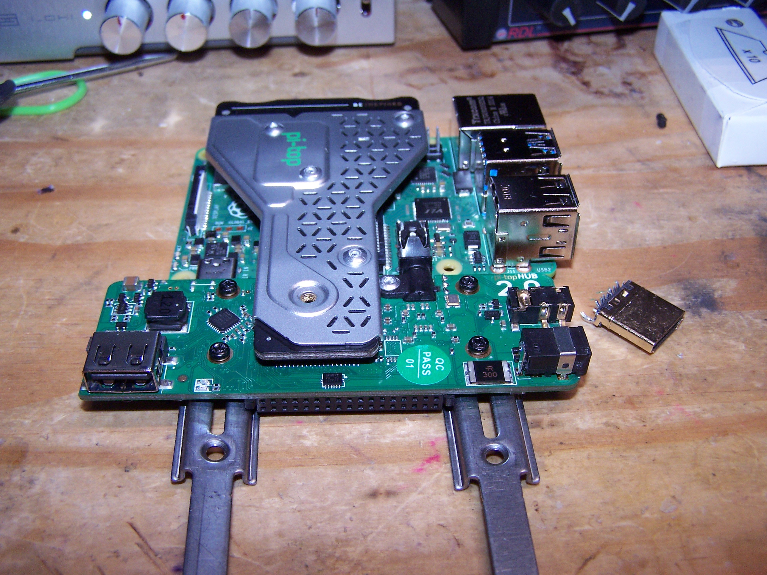
it would need to be short enough to fit under the GPIO/heatsink adapter, and thin enough to allow the boards to mate and make proper electrical contact.
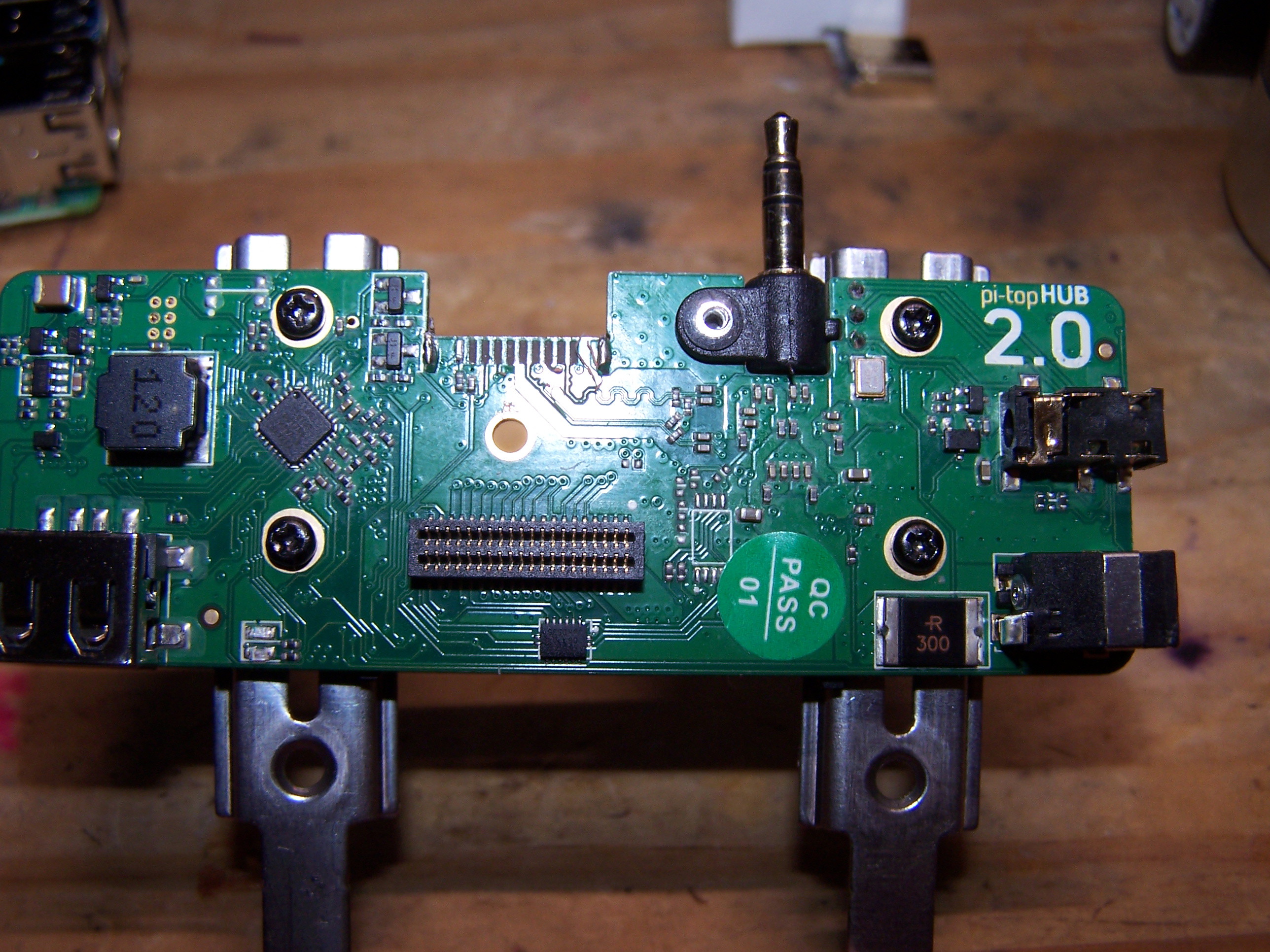
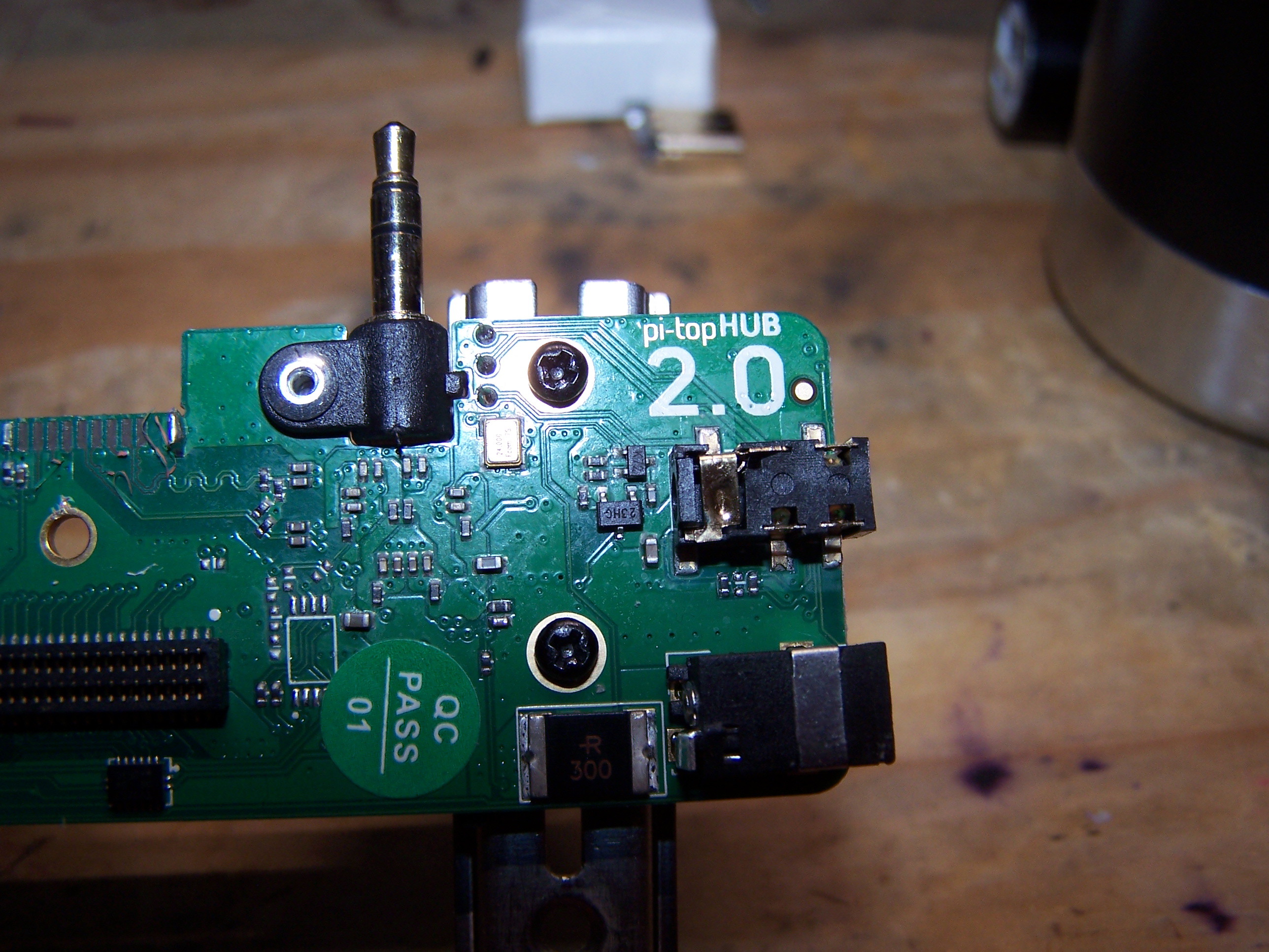
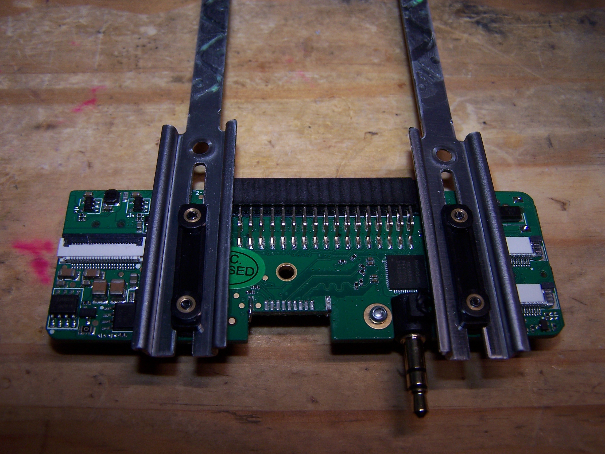
there should be a hole in the adapter board to allow the 3.5mm jack to pass through, though I don’t know if the the thickness of the board would still allow them to mate properly. I know i have seen some amazingly thin cables that could be stiffened with epoxy to make a proto type board. its all passive components pretty much…
to solve the physical port problems. A tool or 2 would be needed. In the packaging trade a diecut metal blade is used to cut custom cartons. Its a sharp bit of steel. Something similiar could be used to cut the connector holes. Using a supplied template/decal to match up to the existing holes, the template could indicate where to drill holes for the tools to cut the hdmi and USB ports would be.
Once the holes are cut a screw would be put thru the hole cutter tool and thru the hole in the pi, a nut is then attached and as the screw is tightened it will cut into the plastic. Optionally the tool could be heated with a soldering iron while cutting to softer the plastic and make the job easier.
this would allow clean holes with minimum effort and calculation regarding where to position them.
such a kit should be feasible for a price point of less than 75$, allowing anyone to get professional results without so much hacking around and perhaps someone could make a few dollars on the project and inspire others…
I know its just brainstorming, but we must start somewhere. I might start by epoxying some of the ribbon cables together to see how thin of a board I can create.
I think this female hdmi might fit under the pi allowing some creative spacing
amazon 6$ femal hdmi full size
any thoughts on this notion?

 and there would be less cutting of cables apart!