
Latest with my mod. A while ago broke the cable going to the screen, so I have found another use for the chassis. Removed the screen and now this is a PiTop 400 Unit (with a mouse), just need to port the HDMI to the chassis and it’s all good to go!
In case you want to use a RPi CM4, rather than RPi4B+, without having to physically modify your pi-top [3], you could use this:
https://www.waveshare.com/product/cm4-to-pi3-adapter.htm?___SID=U
1 Like
Using the board stated above in my build, running Raspbian 5.15.61 kernel atm.
full details are here Pi-top[3] with CM4toPi3 board
Be sure to run below commands in case of using Raspberry Bullseye. This will give you the battery icon and working ‘special keys’ (i.e. Brighthness control)
> echo "deb http://apt.pi-top.com/pi-top-os sirius main contrib non-free" | sudo tee /etc/apt/sources.list.d/pi-top.list &> /dev/null
> curl https://apt.pi-top.com/pt-apt.asc | sudo apt-key add
> sudo apt update
> sudo apt install --no-install-recommends -y pt-device-managerCan’t figure out why my PI4 won’t boot up. Have the HDMI and ribbon cables extended but power LED only flashes green three times and goes back to red. PI4 works fine on it’s own. Any suggestions?


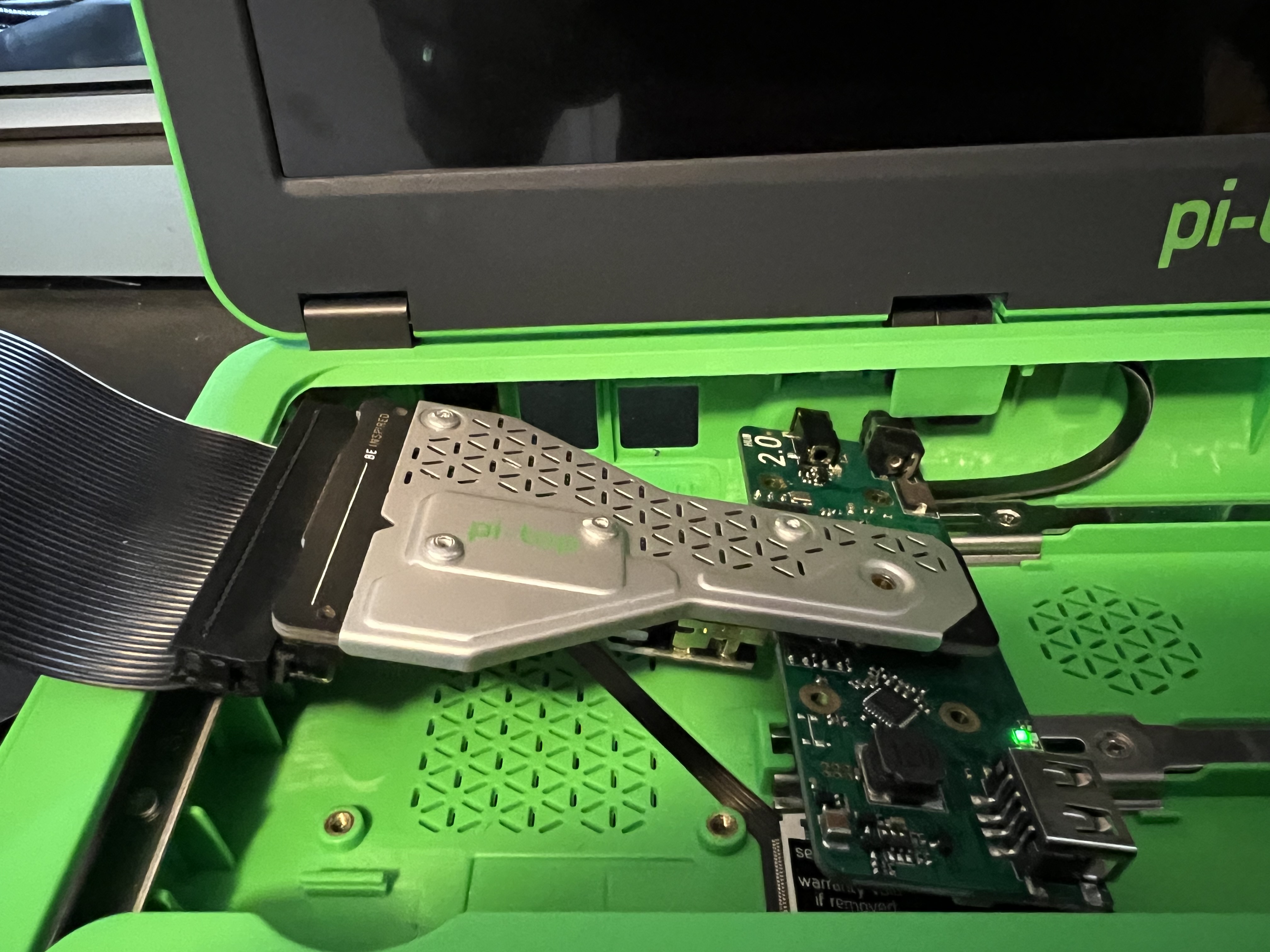
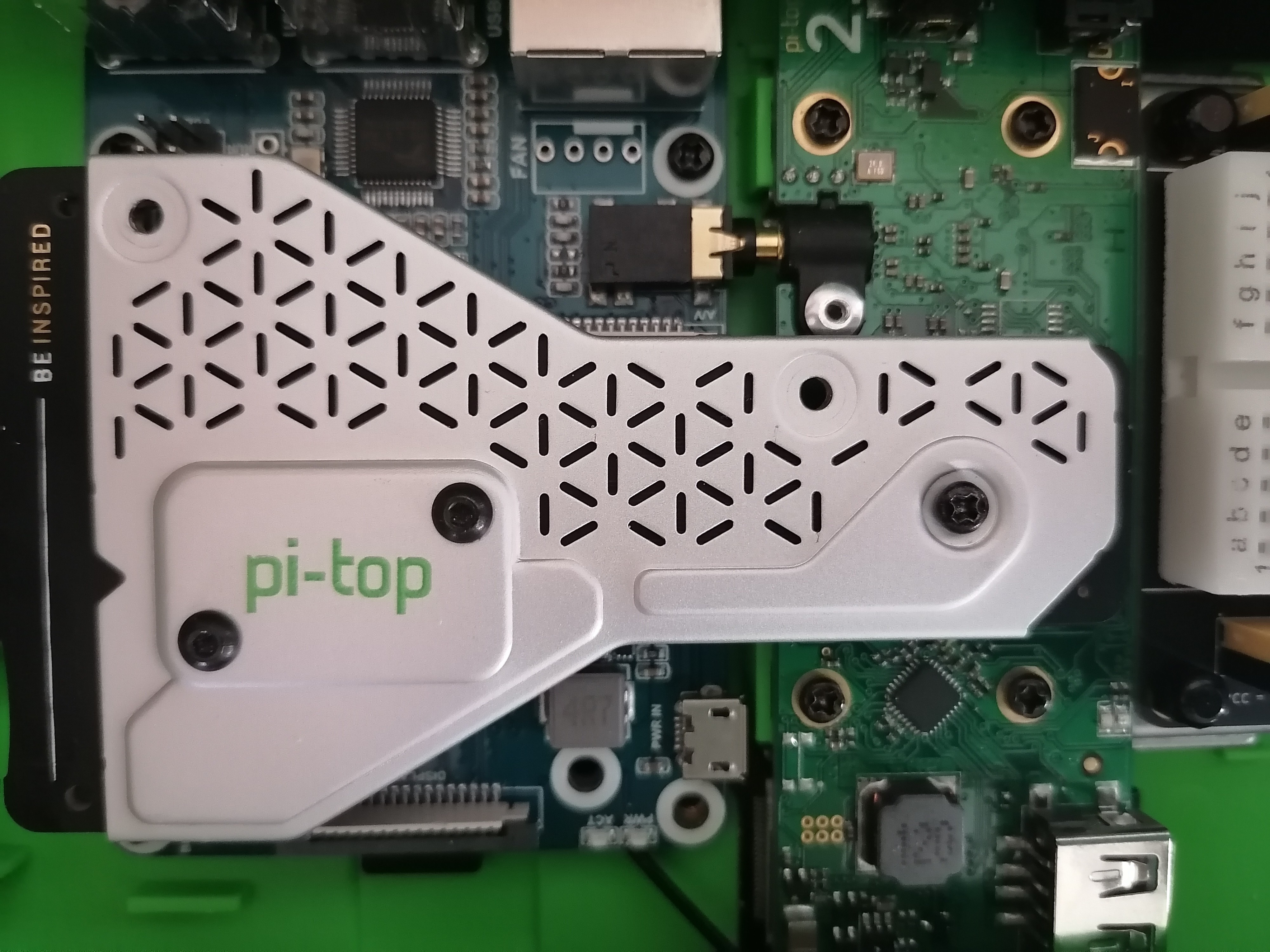
Check the connection of the bridge board, it can be miss-plugged
double/triple checked all of the cables on the board. Removed and reinstalled the ribbon cables - all looks good. The hub seems to be secured as possible to the board as well. Tested with a Pi Zero just for the hell of it with same results. Don’t have a Pi 3, so unable to see if it’s a problem specific to the hub or board.
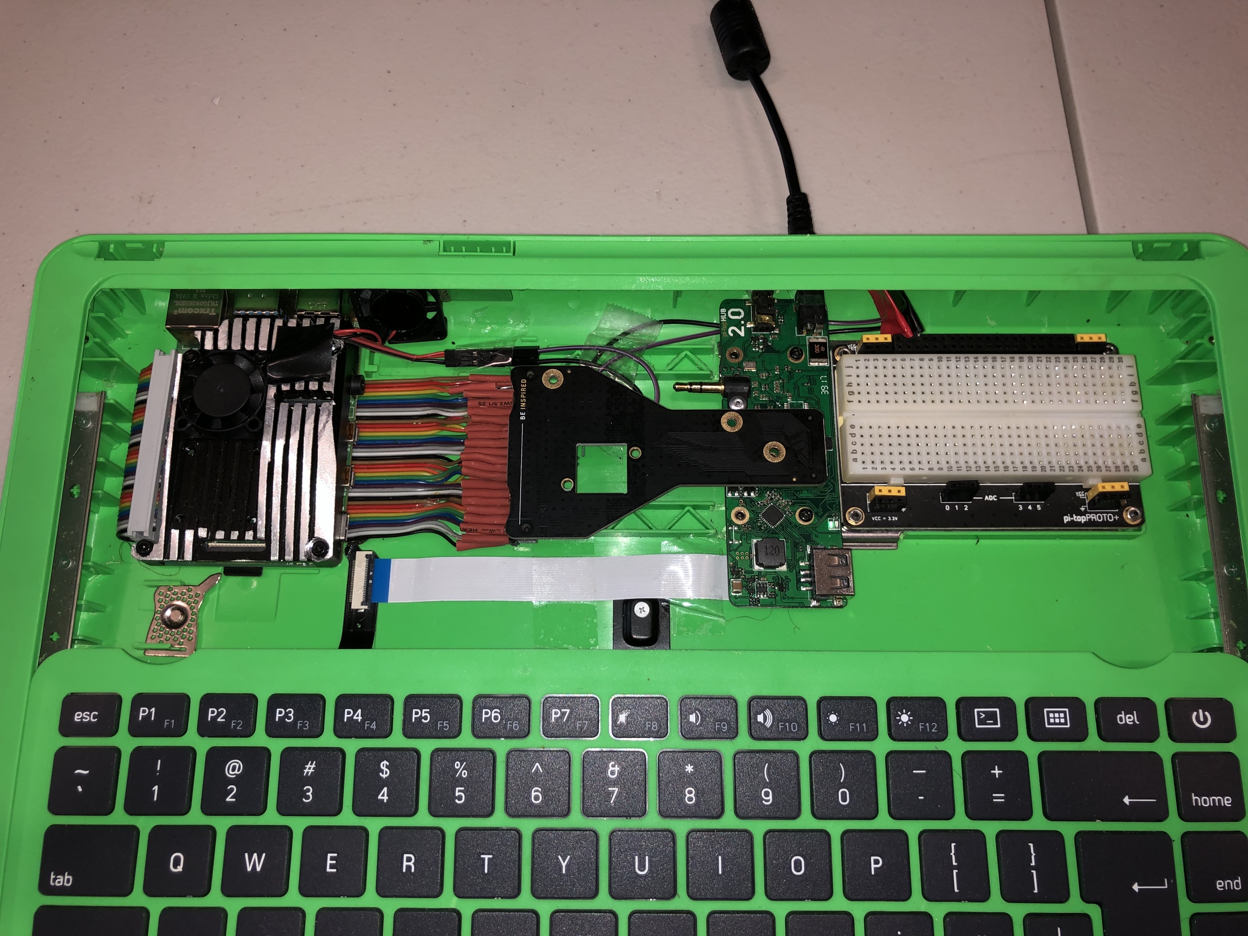
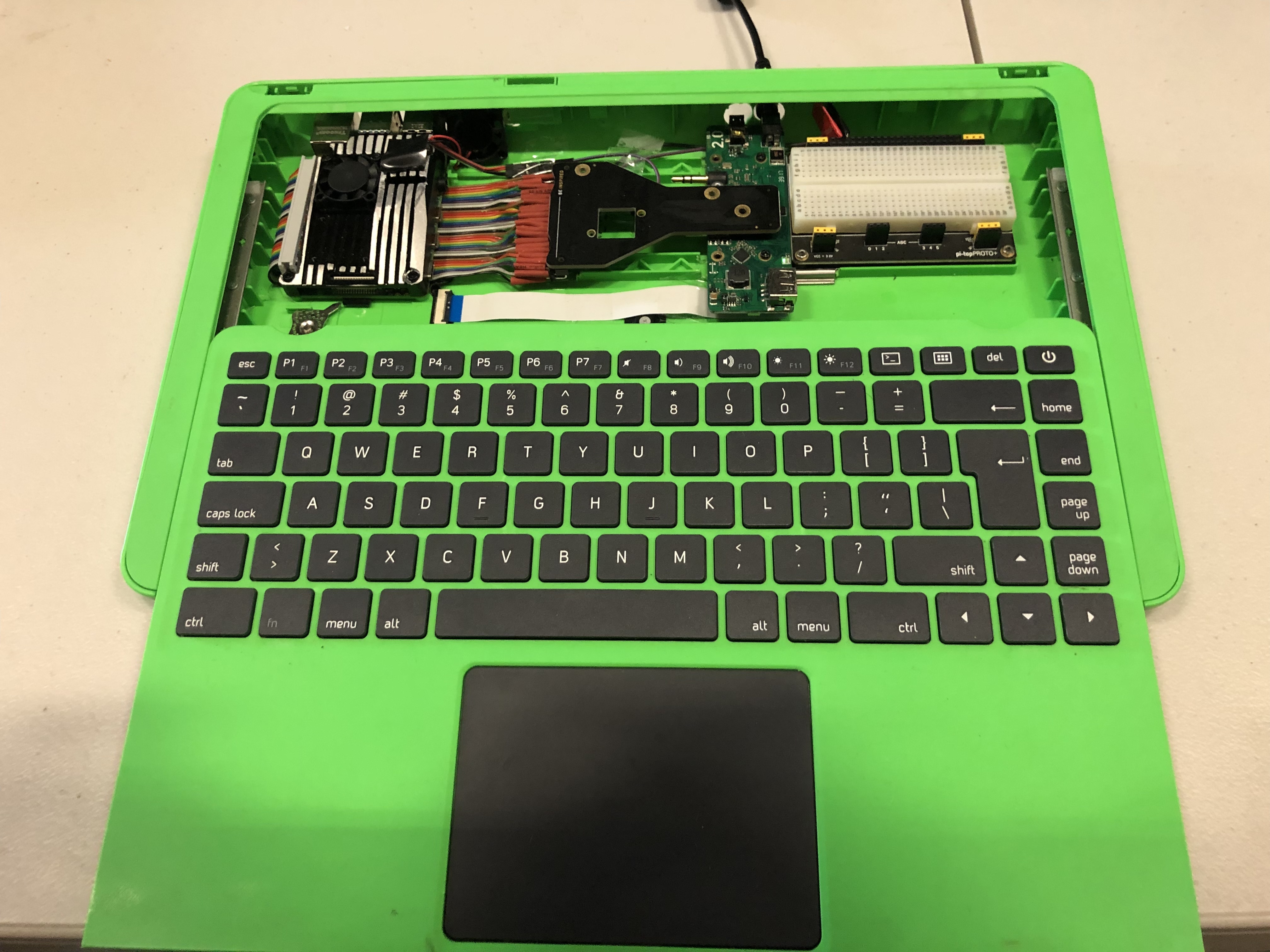
It’s hard to tell from the pictures, but to me it looks like the bridge is offset to the right. Check if you can insert the screw.
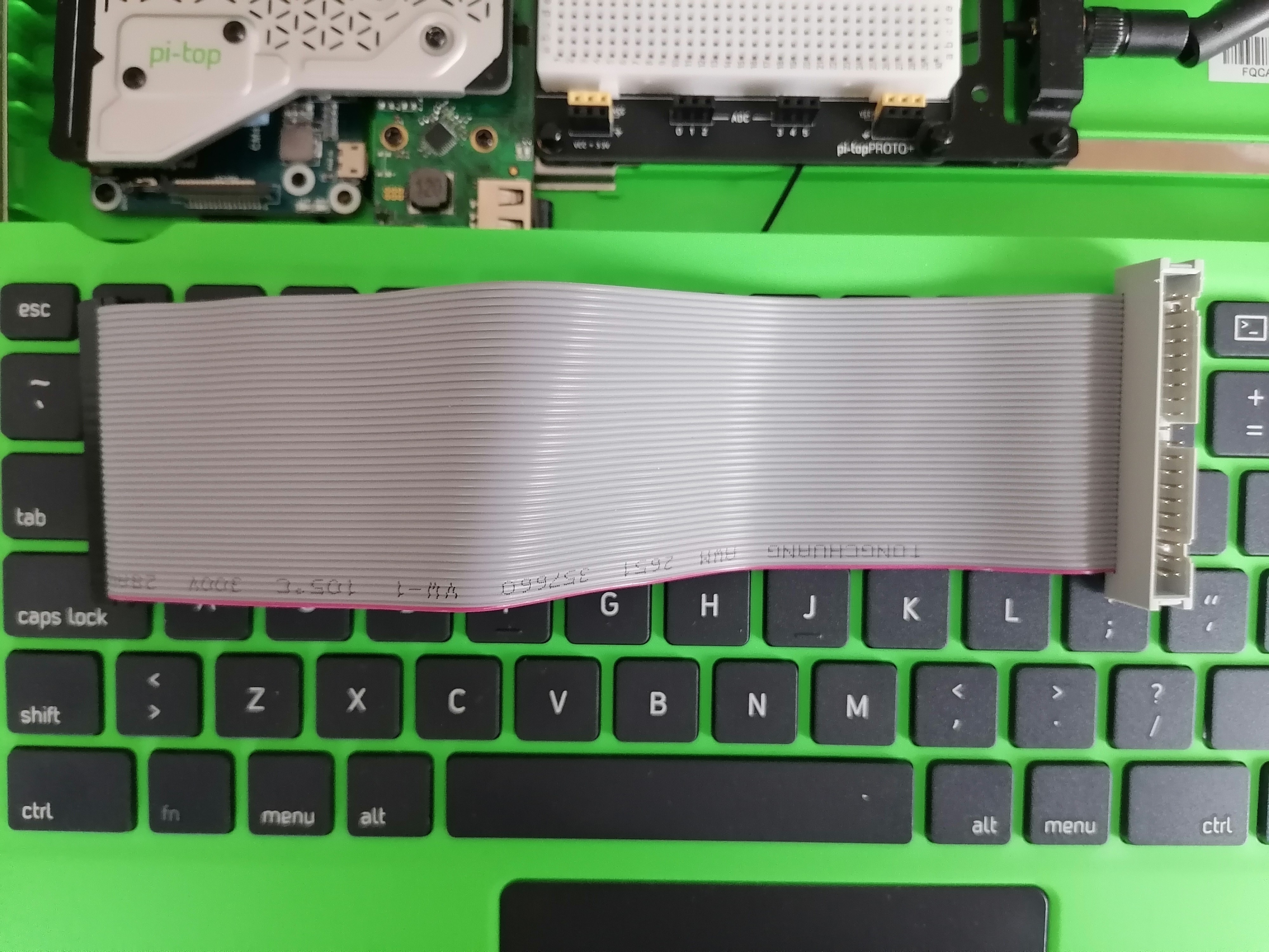
Also your flat wire cable looks odd. The white side is typ. used as Pin1 indicator; you have it the other way around. have you measured your GPIO40 before you’ve connected the bridge? Is Pin1/2 in the correct position?
I’ve mad a similar test but used a different cable like https://shop.pimoroni.com/products/40-pin-gpio-extension-cable?variant=32246715580499 -> please mind their note in the product description!
1 Like
Looks like it was the cable. Also got a thin ribbon USB cable. Working like a charm. Thanks for the help!
I seem to have scored a couple of CM4 boards, so I bought a couple of the CM4 to Pi 3B adapters. Has anyone tried to build a Pi-Top with one of these setups yet? I’m pretty sure it will fit (maybe a little bit high, but within coping distance). Heat: It looks like the CM4 SOC metal chip lid will be hard against the green plastic bottom of the laptop. I don’t have any great ideas for this. I could cut a window in the bottom, but I don’t think that would be very effective. I’m not going to use this as a compute cluster, but… Hmm. How about a thin aluminum heat spreader like the Pi-400? It would have to thin, but maybe that would be a reasonable solution and keep the bottom of the laptop intact. I also have one of the aluminum Astro-Pi cases, that take Pi 3’s, so I am hoping the Waveshare adapters are good.
rpiMike posted about this in the above thread.
Don’t do this. Don’t spend your money until we come up with some better way.
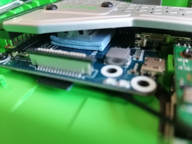
Given the Waveshare CM3 to Pi 3B adapter, which mounts the CM4 on the bottom, it just plain does not fit. @Tom-B, above had to cut a whole in the bottom of the laptop the full size of the CM4. From my efforts to just squeeze it in somehow, I think he’s exactly correct about this. There are several problems, but the big one is heat. It can’t use any heatsinking from the metal bridge, and just cutting a hole in the bottom isn’t going to allow convection.
I was hoping to get it to just fit and then buy some aluminum sheet material to make a heat spreader across as much of the case bottom as I could. That’s how the pi-400 does it.
Can’t second this!
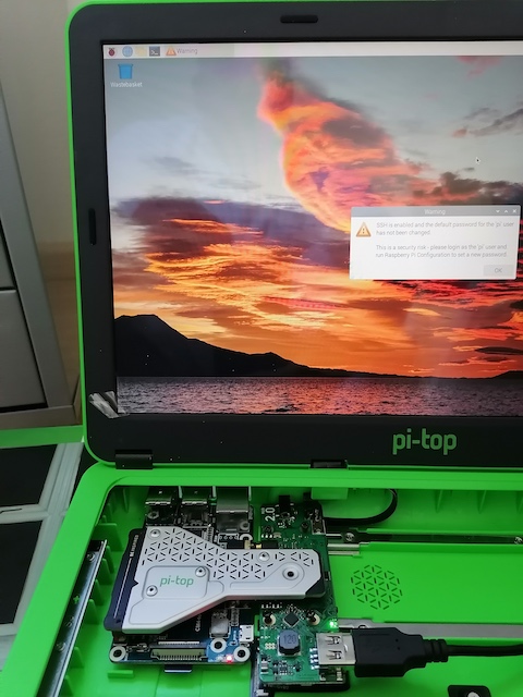
Also made such a mod, covering the resulting hole with a piece of GFK.
The PI is just working fine. Keep in mind that a CM4 is designed to work without cooling.
Adding a alu plate (with some TIM material to the SOC) will result in the alu getting hot to the touch! One can burn its finger touching it.
Having the CM4 on top of the carrier would be beneficial, but there is no such carrier around.
For more powerful boards than the libre alta, the easiest solution seems to be this: https://www.waveshare.com/zero-to-pi3-adapter-a.htm
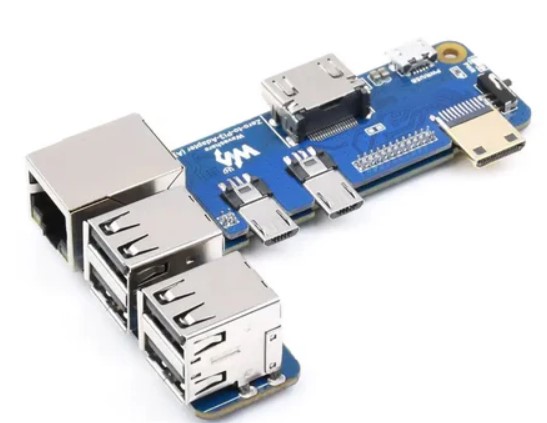
Pi zero to 3b adapter, this maintains all rear ports.
Then use a 40 pin GPIO extender, 2x USB C female to USB A male extenders, Micro HDMI female to HDMI male extender and audio extension cable.
This should make it possible to place the new board in the right hand side of the case.
1 Like
I was wondering where you were going with this until I read this sentence! It’s a pity that this adapter lacks the 3.5mm A/V port for it to be a truly drop-in adapter for the hubv2 in the pi-top [3]. It’s also a pity that Waveshare has no plans to make such an adapter board (not even the CM4 --> RPi3B+ adapter board) with USB3…
Which more powerful SBCs do you have in mind? The Radxa Zero 3? Although this has up to 8Gb RAM (double the max of the Libre Computer Alta), Geekbench 6 and Gadgetversus would seem to indicate that the A311D in the Libre Computer Alta is about twice as powerful as the RK3566 in the OrangePi 3B (and in the Radxa Zero 3). Though the performance per Watt is slightly lower for the A311D than the RK3566.
Also, the die size for the A311D is 12nm, whereas the RK3566 is 22nm so the Alta should have better thermals? That might be a slightly muddied picture by the RK3566 having a 2W lower TDP than the A311D. If more tasks can be offloaded to the GPU then the A311D should definitely come out far ahead.
I’m thinking of trying to build a “Franken[3]” using either an official R Pi4 or 5 (Full Sized) OR a CM4/CM5 + Carrier Board / Adapter (eg a Waveshare board.) It looks like more or less the same effort involved in each (relocating USB FFC from the back, cutting out the case hole, adapting HDMI from bridge) so it would be more a matter of features + extras. I really like using M.2 drives at pcie speeds so I lean toward the pi5. Currently using a Pi5 + m.2 + active cooling in a pi-top[1] which was very easy to setup physically, running Raspbian and it works great. With pi5 it helps that I have the board (unlike CM4/5 + Carriers/Adapters.) But I’d consider the compute module approach if someone recommends. Any recommendations on the approach?
1 Like
Also, if anyone has parts left over from a Franken[3] build that they no longer want, specifically 1) ribbon cables for the bridge or 2) HDMI adapters, would be happy to pay you for them plus shipping & handling (in Western US. /WA)
There are quite a few RK3576 (Banana Pi m5 PRO) and RK3588 (Orange Pi 5 Plus, Radxa Rock 5B Plus) boards out now.
Also A311D2 is available at least in the Khadas vim4.
RK3588 doesn’t have full mainline support yet but is pretty powerful, unfortunately too power hungry to be practical in pi-top without power delivery mods.
Sorry, I meant specifically which more powerful boards did you have mind which could be retrofitted in the pi-top [3] by using the Waveshare adapter you recommended? The only powerful Zero form factor SBCs I can think of are the Geniatec XPI-3566-Zero and Radxa Zero 3W, both based on the RK3566 but whilst they can have up to 8Gb RAM (vs the A311D’s 4Gb), the A311D is actually more powerful and the port layouts on those RK3566-based Zero alternatives wouldn’t fit the Waveshare adapter… There is the A311D-based Radxa Zero 2 Pro but that also has the same issue with port layout.
On the subject of RK3576, would you be willing to comment in the Radxa Rock 4D thread?