
Yep, a microscope is key - although it never ceases to amaze me what people can do without a microscope 
i’ve been thinking about this dilema, and it seems there are 2 issues
1 the physical port problems
2. the connector mismatch
1 think the connector mismatch could be solved with a custom board. it would need to insert at 90 degrees to the other 2 boards (pi 4 and bridgeboard) so it would be edgewise
compared to the others.
it would have 2 micro hdmi male plugs on one side and full size hdmi female port to mate to the bridgeboard. 1 micro-hdmi would provide video to the lcd through the bridgeboard, the 2nd would supply a connection for an external monitor at the rear of the pi-top. so the card would have a micro hdmi or whatever is easiest to wire at the back of
probable rotated 90 degrees to match the orientation of the adapter board.
it could be a printed circuit board with any line buffering provided by smd components.
it would need to be short enough to fit under the GPIO/heatsink adapter, and thin enough to allow the boards to mate and make proper electrical contact.
there should be a hole in the adapter board to allow the 3.5mm jack to pass through, though I don’t know if the the thickness of the board would still allow them to mate properly. I know i have seen some amazingly thin cables that could be stiffened with epoxy to make a proto type board. its all passive components pretty much…
to solve the physical port problems. A tool or 2 would be needed. In the packaging trade a diecut metal blade is used to cut custom cartons. Its a sharp bit of steel. Something similiar could be used to cut the connector holes. Using a supplied template/decal to match up to the existing holes, the template could indicate where to drill holes for the tools to cut the hdmi and USB ports would be.
Once the holes are cut a screw would be put thru the hole cutter tool and thru the hole in the pi, a nut is then attached and as the screw is tightened it will cut into the plastic. Optionally the tool could be heated with a soldering iron while cutting to softer the plastic and make the job easier.
this would allow clean holes with minimum effort and calculation regarding where to position them.
such a kit should be feasible for a price point of less than 75$, allowing anyone to get professional results without so much hacking around and perhaps someone could make a few dollars on the project and inspire others…
I know its just brainstorming, but we must start somewhere. I might start by epoxying some of the ribbon cables together to see how thin of a board I can create.
I think this female hdmi might fit under the pi allowing some creative spacing
amazon 6$ femal hdmi full size
any thoughts on this notion?
How is the NanoPi M4V2 working out in the pi-top? I have been looking for a CM4 carrier with a pi3 form factor, and do not see one. So maybe the NanoPi M4V2 is a good alternative. Is heat management OK? I understand this board can get a bit warm.
I need to know how the keyboard’s power button reaches the pc-board that is not the bridge. Ideally, there’s a pin-out for the connector, or you could just tell me what pins are involved. I hope it’s not a serial message of some kind. I thought I was on a roll.\
My current Franken idea is basically the guts of the [3] removed from the case, and using the rails for both of the proto-board modules. Then, OOOPS!, I got the parts out of the laptop, and realized that the reason it will not power up is that the power button is on the keyboard.
I’m loving the proto-plus board, by the way. That six-input analog-to-digital converter really adds a lot. It works great for me. I’ve tweaked the common Adafruit Python library to remove most of the wait time. I was trying to monitor something I’m designing and realized that the proto-plus was the only DC-coupled A-to-D item that I had in the house.
I had a similar conversation with another user recently here - let me know if this provides enough info
Thank you very kindly for your response. That’s a Pi-Top 1, (I have several) but I’m working with the 2/3 green laptop. Ideally I need to know what pins on the connector that attaches to the ribbon from the keyboard need to be shorted or whatever. Maybe there are even macroscopic (compared to those very small pins) that would be easier to solder to as suggested in that thread. Unfortunately, I don’t think I have that power button board, but I haven’t opened up the keyboard yet.
Oh sorry! I misread it completely - let me have a look what you can do and get back to you
Can you send me a picture of your board? I want to see what version it is
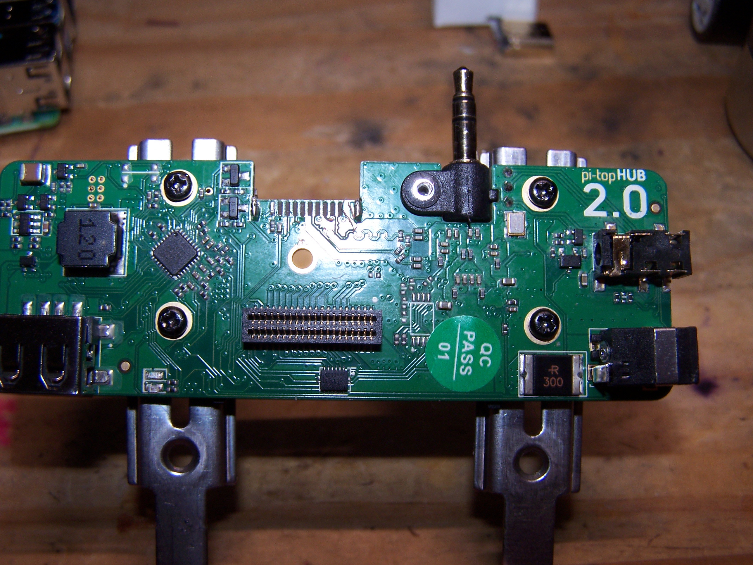
I agree. There’s nothing like a good picture to make sure we’re talking about the same thing. I’ve been assuming that the keyboard comes in via the wide white ribbon cable socket on the left of my shot of the bottom of the hub board. I just read tonight on this forum about the USB connections to the laptop shell. I don’t know what I am missing by not having those. I could extract them, too, and come up with some way to fit them to the Pi 4B. That loose HDMI connector on my desk is the one I pulled off the hub board so that it could make with a Pi 4B.
Eirikur
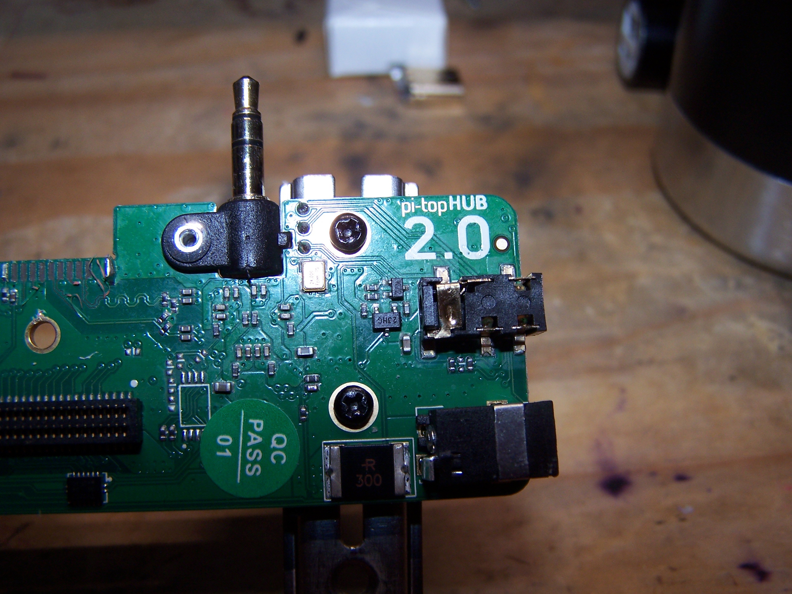
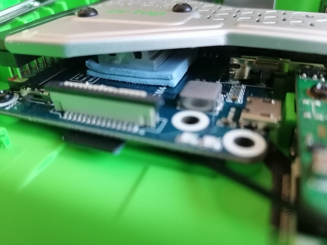
We have a place to mount a power button here:
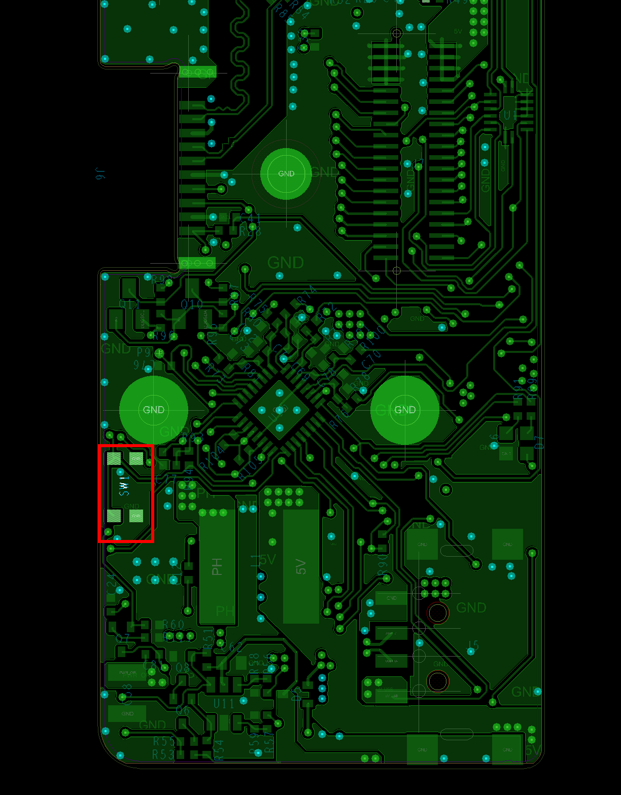
We added it for development purposes so you could use that, here’s a close up of the pins:
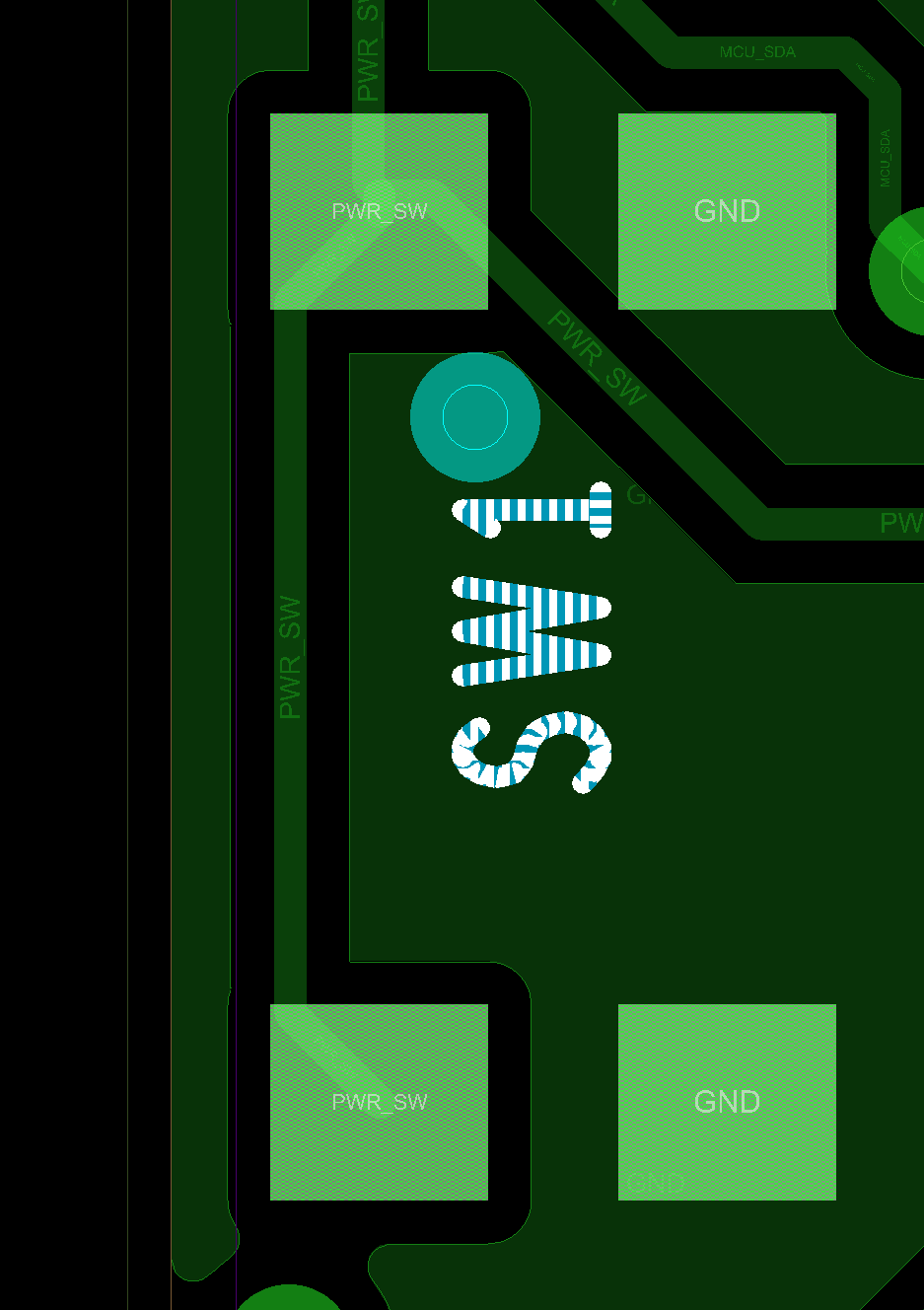
The part number for this switch is KMR731NG - you should be able to get one easily and soldering won’t be that difficult 
Thank you very much! I’m excited to get going on this again. This is above the call of duty. If I can make your management aware, I’d be glad to.
1 Like
No worries, glad to help!
New user here - I’ve been considering all of the options for converting to pi4, and they all have their benefits and drawbacks.
The method that @JeffS451 used is just the business, and I nearly went that way, but having soldered more than a few HDMI cables recently, I got cold feet. HDMI is super sensitive to interference between the wires, so even a mistake free solder job could end up giving a “noisy” image, or just not working.
@Steve has a setup that I like, and I may just go with that - already have the necessary FPV cable parts, and a longer 20pin FPC cable coming for the battery/keyboard connection to the hub.
But I had an idea, and I was wondering if it was absurd or no. with the full cooling bridge in place, the hub 2.0 has to sit pretty far away from the pi. I also don’t really care about preserving the GPIO pins into the modular rail - I only need SDA and SCL to allow interaction with the hub, and power/ground/board detect. I looked for the right BTB 0.8mm 2x20 4mm mated vertical post socket to whip up a custom bridge with just those connections, but that proved fruitless. The closest I could find that looked correct was $20 for a single piece.
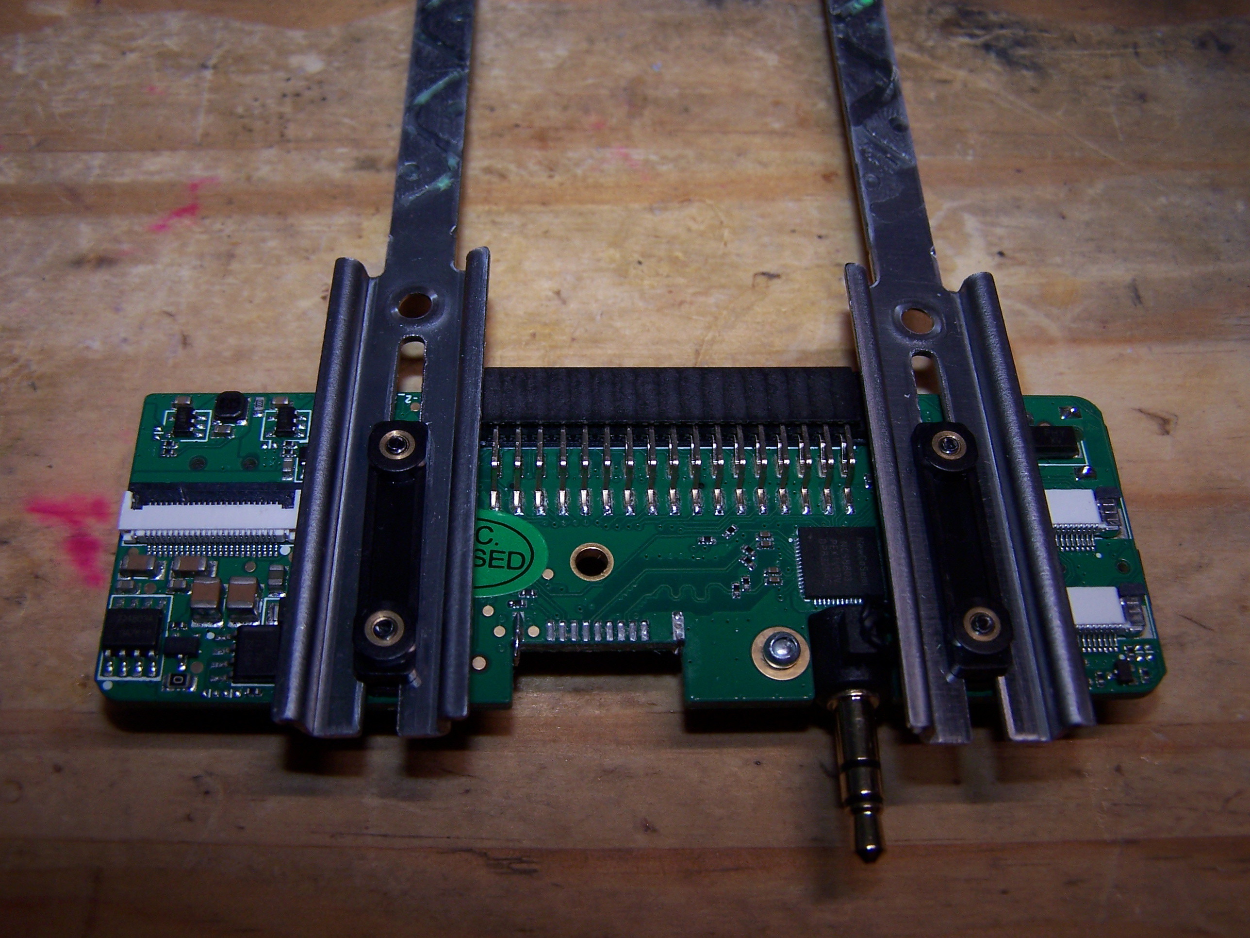
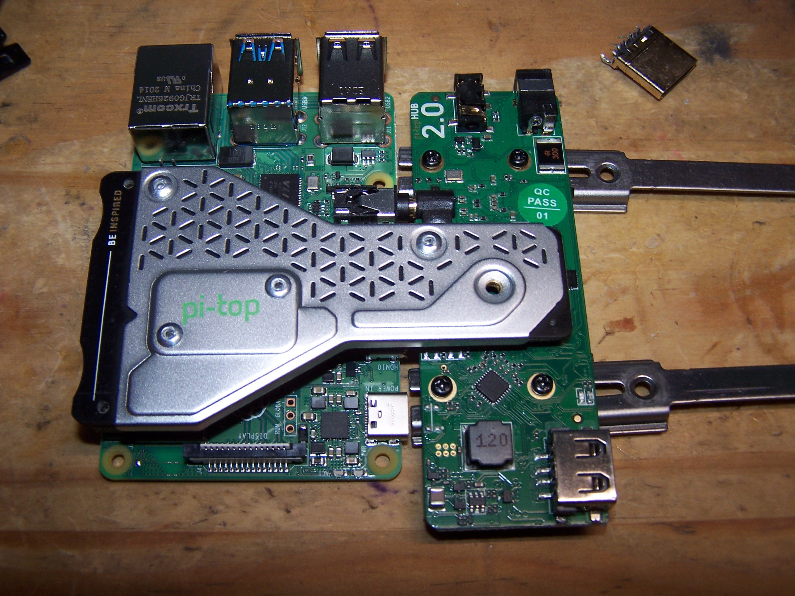
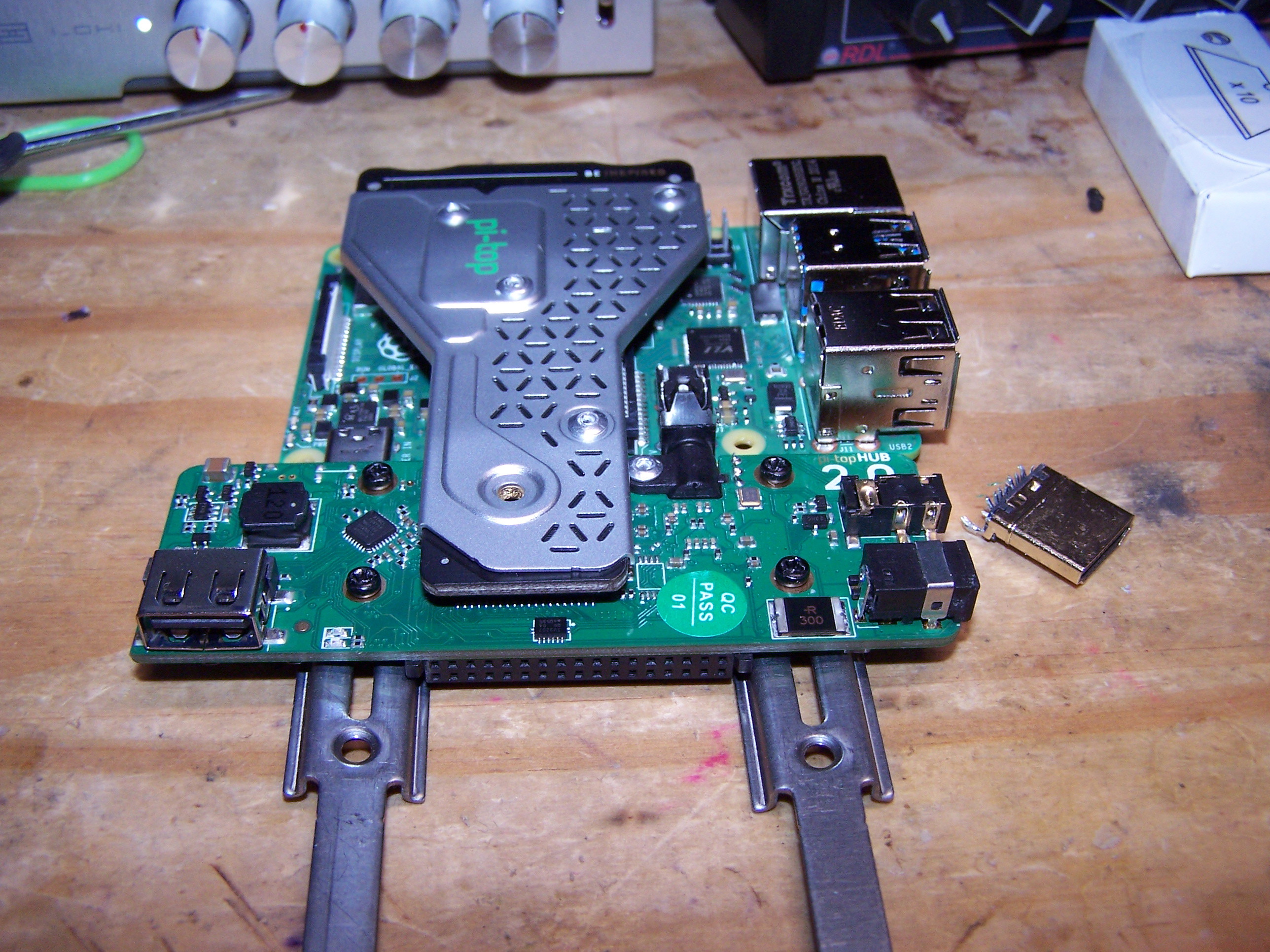
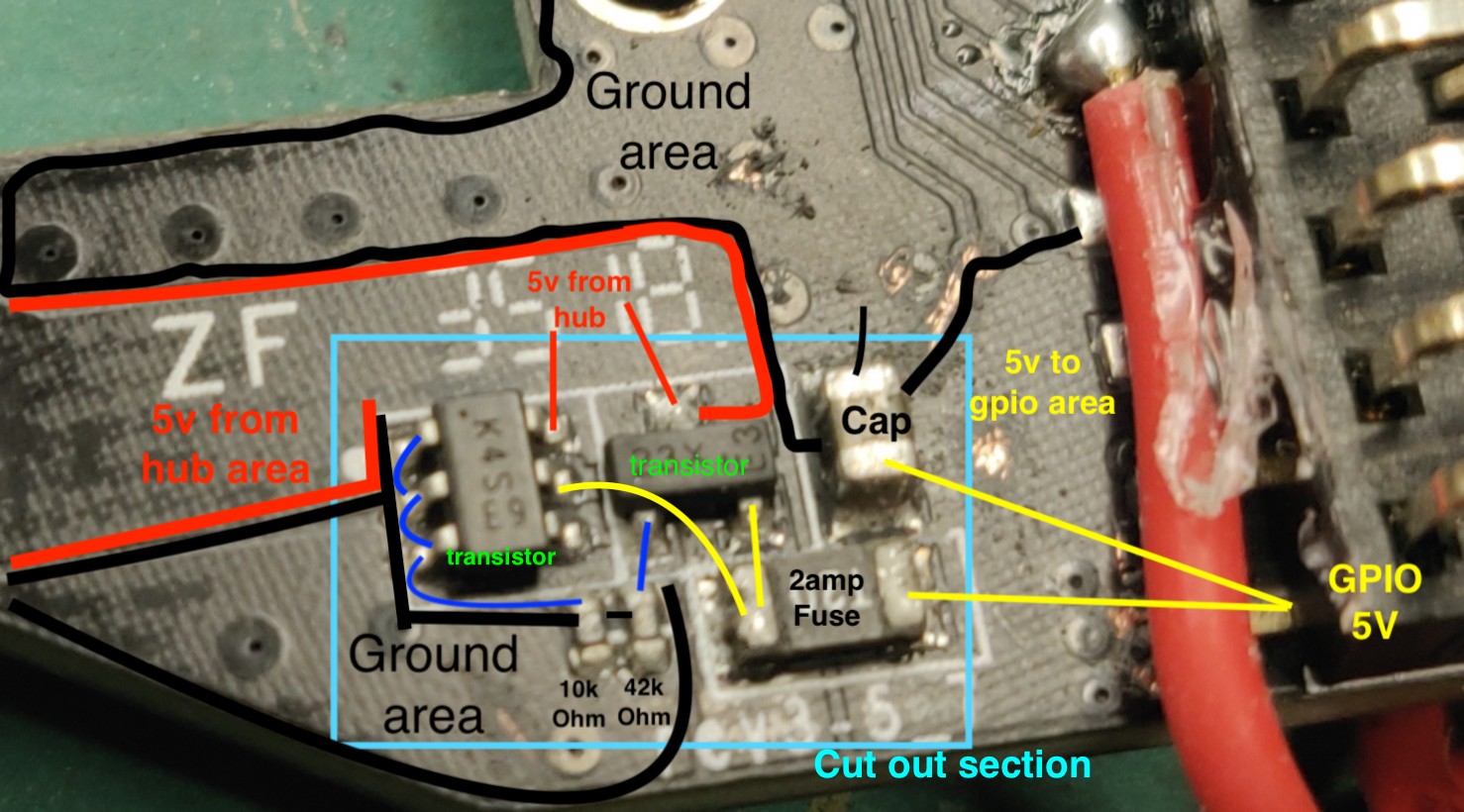
Then I thought, why not hack up the stock bridge? Just keep a section big enough to cover the hub, and solder to the appropriate traces, which I found with a magnifying glass, razor to expose some traces, and a multimeter. Seems like it could work just soldering the cut end of a Dupont wire to those traces/ground for the five necessary wires, and simply plugging the dupont ends in on the pi4.
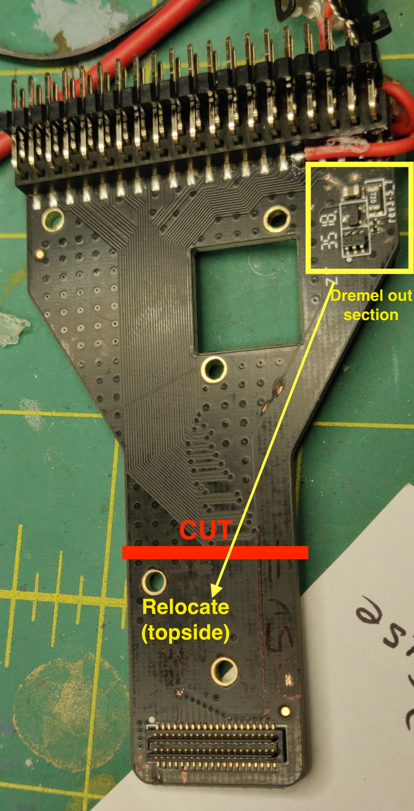
But then I had to deal with the power circuit on the bridge. That straddles a 5v path to the pi GPIO pins on one side, and the 5v path from the hub on the other. I’m thinking I could dremel that section out whole, and glue it to the top of the amputated hub end of the bridge, then jump a ground wire and each 5v path up to it. With the 2x20 female gpio section of the bridge removed, that would mean the hub could go right up close fo the pi - even straying on the sliding portion of the rail.
So far as I can gather, it should work - but maybe I’m missing something about that power circuit.
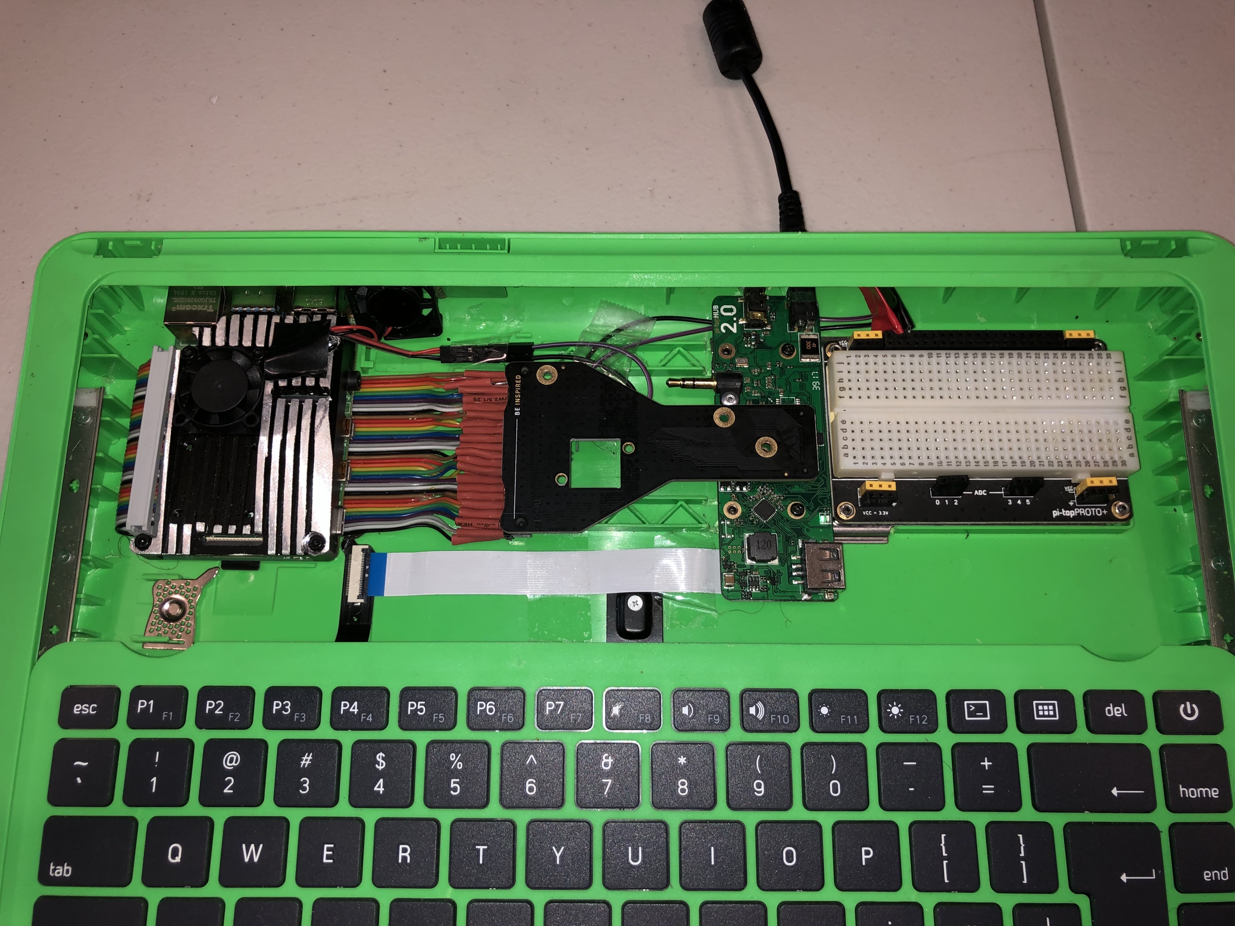
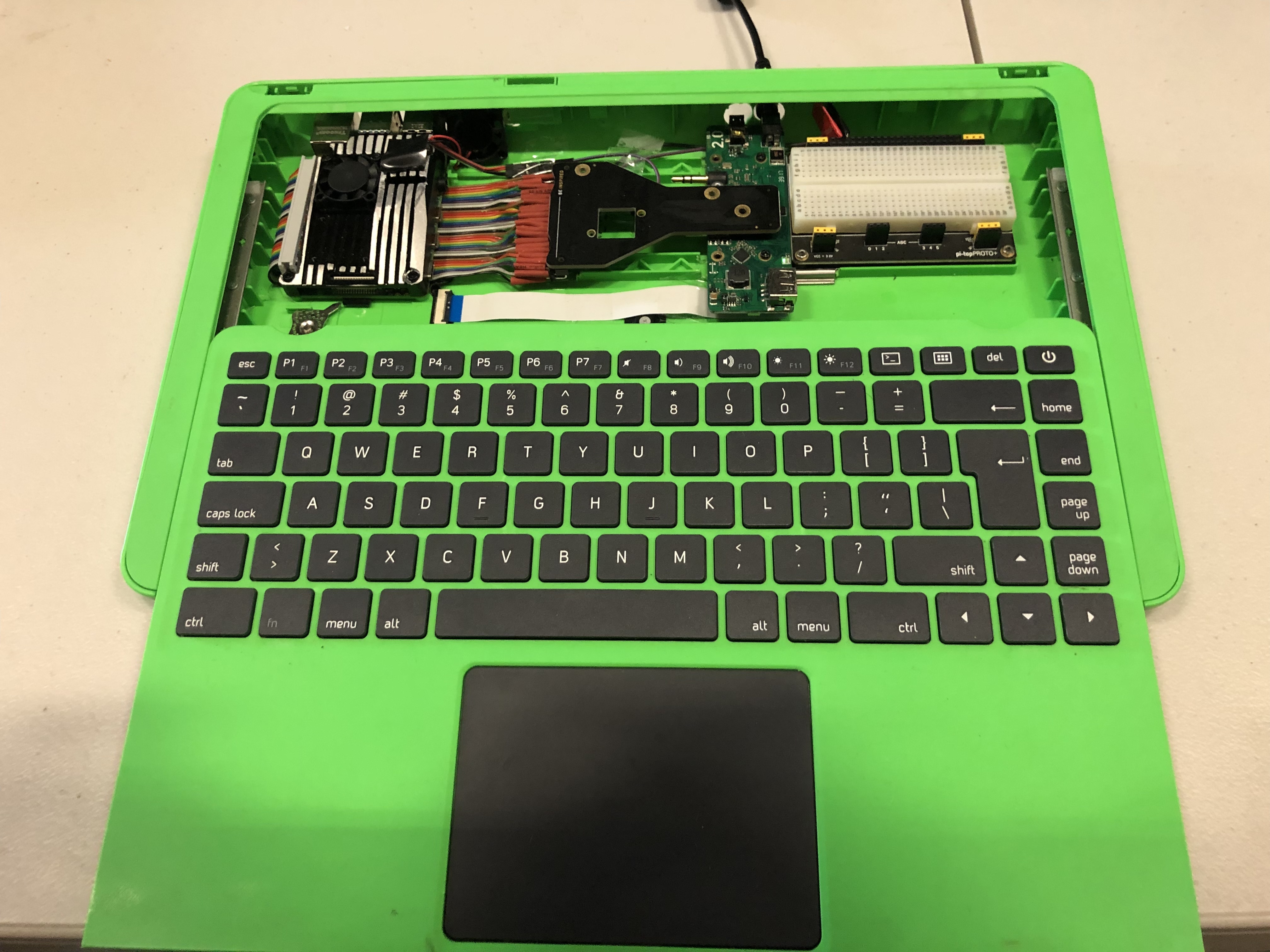
*note the red wire in the pics is connected to a toggle switch that brings board detect to ground. Wanted to see the pi-top boot without a pi connected - which it did, though I was unable to get a video signal to display on the screen with two different sources? For one it played a sort of screensaver type effect for a couple of seconds, but never did display an image, though the video sources (iphone with hdmi out, and macbook, both set to 1080p) saw the display as connected.
Hello! I really like watching the various efforts being made to up the power of thepi-top [3]. Personally I suspect that if they just released the part that plugs into the the side of the Raspberry Pi 4, the folks who play here would figure the rest out  and there would be less cutting of cables apart!
Latest with my mod. A while ago broke the cable going to the screen, so I have found another use for the chassis. Removed the screen and now this is a PiTop 400 Unit (with a mouse), just need to port the HDMI to the chassis and it’s all good to go!
In case you want to use a RPi CM4, rather than RPi4B+, without having to physically modify your pi-top [3], you could use this:
https://www.waveshare.com/product/cm4-to-pi3-adapter.htm?___SID=U
1 Like
Using the board stated above in my build, running Raspbian 5.15.61 kernel atm.
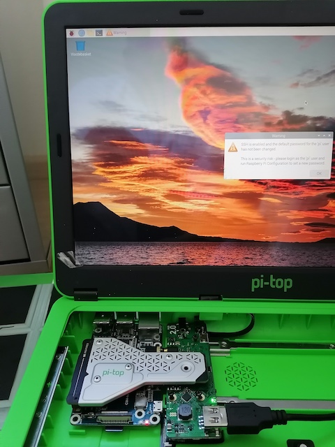
full details are here Pi-top[3] with CM4toPi3 board
Be sure to run below commands in case of using Raspberry Bullseye. This will give you the battery icon and working ‘special keys’ (i.e. Brighthness control)
> echo "deb http://apt.pi-top.com/pi-top-os sirius main contrib non-free" | sudo tee /etc/apt/sources.list.d/pi-top.list &> /dev/null
> curl https://apt.pi-top.com/pt-apt.asc | sudo apt-key add
> sudo apt update
> sudo apt install --no-install-recommends -y pt-device-manager